Binder for formation of ceramic or for use in conductive paste, and use of same

a technology of binders and ceramics, which is applied in the direction of electrically conductive paints, non-conductive materials with dispersed conductive materials, manufacturing tools, etc., can solve the problems of increasing the amount of binder resin to be used, poor adhesiveness, and insufficient electrical properties of shaped objects, etc., to achieve excellent storage stability, improve the adhesiveness of pressure bonding of lamination, and improve the effect of adhesiveness

Inactive Publication Date: 2017-01-12
KURARAY CO LTD
View PDF2 Cites 2 Cited by
  • Summary
  • Abstract
  • Description
  • Claims
  • Application Information

AI Technical Summary

Benefits of technology

The present invention provides a binder for ceramic formation that is stable and has a small amount of carbon residue after sintering. When used in a conductive paste, the binder improves adhesiveness and results in a sintered body with less carbon residue.

Problems solved by technology

When the dispersibility or the storage stability of the ceramic slurry is insufficient, a ceramic green sheet produced therefrom may have insufficient density, smoothness, and the like, resulting in poor adhesiveness.
When there is a large amount of carbon residue in a shaped ceramic article after sintering, the shaped article may have insufficient electrical properties and the like.
However, when ceramics powder having a fine particle size is used, the packing density and the surface area increase, causing an increase in the amount of binder resin to be used.
Accordingly, the viscosity of the slurry composition for a ceramic green sheet is increased, so that coating sometimes becomes difficult or the ceramic powder itself may be dispersed poorly.
Meanwhile, there is limitation in downsizing of a stacked ceramic capacitor, and in order to increase in capacity or downsize while keeping the capacity of the stacked ceramic capacitor, the green sheet is required to be multilayered in addition to be thinner.
However, in the step of pressing the green sheets for lamination, stronger press causes deformation in such green sheet and a conductor layer, and higher precision required for the stacked ceramic component is not achieved.
On the other hand, weaker press in a conventional manufacturing method causes a weaker adhesion force between the green sheets or a green sheet and a conductor layer, resulting in upper and lower green sheets not closely adhering.
When such poor adhesion occurs, there is a problem of generating a defect after sintering of the ceramic lamination to reduce the reliability of the component.
In addition, in the step of transferring a conductor layer from the carrier film to the green sheet by pressing, stronger press causes deformation in the conductor layer and the higher precision required for the stacked ceramic component is not achieved.
In spite of that, weaker press in a conventional manufacturing method causes a weak adhesion strength between the green sheet and the conductor layer, resulting in the conductor layer not closely adhering to the green sheet.
When such poor adhesion occurs, there is a problem of, not only failure in conductor layer formation, generating a defect after sintering of the ceramic lamination to reduce the reliability of the component.
However, the ceramic paste and the slurry composition according to Patent Reference Nos. 1 and 2 sometimes have insufficient storage stability.
In addition, there may be a large amount of carbon residue in shaped ceramic articles obtained from them, and the shaped articles may have insufficient electrical properties and the like.
When the storage stability of the conductive paste is insufficient, the printability becomes worse during printing of a conductive paste on the surface of a ceramic green sheet and the smoothness of the printing surface becomes poor.
When there is a large amount of carbon residue, the sintered body has insufficient electrical properties and the like.
However, a conductive paste using the binder for a conductive paste according to Patent Reference No. 5 has insufficient storage stability.
In addition, there is a large amount of carbon residue in the sintered body thus produced and the performances are insufficient.

Method used


Image

  • Binder for formation of ceramic or for use in conductive paste, and use of same

Examples


example 1

[0196]In a 10 liter glass vessel equipped with a reflux condenser, a thermometer, and an anchor type impeller were charged 8100 g of ion-exchanged water and 660 g of PVA-1 (PVA concentration: 7.5%), and the contents were heated to 95° C. to completely dissolve the PVA. Then, the contents were gradually cooled to 10° C. over about 30 min. with stirring at 120 rpm. Then, to the vessel were added 384 g of n-butyraldehyde and 540 mL of 20% hydrochloric acid, to carry out a butyralation reaction for 150 min. Then, the mixture was heated to 60° C. over 60 min., kept at 60° C. for 120 min., and then cooled to room temperature. The precipitated resin was washed with ion-exchanged water, followed by adding an excessive aqueous solution of sodium hydroxide for neutralization. Subsequently, the resin was again washed with ion-exchanged water and then dried to provide polyvinyl butyral (PVB-1).

(Composition of Polyvinyl Butyral)

[0197]With regard to polyvinyl butyral, a degree of butyralation (de...

examples 2 to 8

[0225]Polyvinyl butyral was synthesized as described for Example 1, except that the starting PVA was changed as shown in Table 6. Then, the storage stability of the ceramic slurry, the amount of carbon residue in the ceramic green sheet, the storage stability of the conductive paste, and the amount of carbon residue in the conductive paste were evaluated as described for Example 1. The results are shown in Table 6.

example 9

[0226]Polyvinyl butyral was synthesized as described for Example 1, except that the amount of n-butyraldehyde was changed to 320 g. Then, the storage stability of the ceramic slurry, the amount of carbon residue in the ceramic green sheet, the storage stability of the conductive paste, and the amount of carbon residue in the conductive paste were evaluated as described for Example 1. The results are shown in Table 6.


PUM

PropertyMeasurementUnit
Temperatureaaaaaaaaaa
Timeaaaaaaaaaa
Nanoscale particle sizeaaaaaaaaaa

Abstract

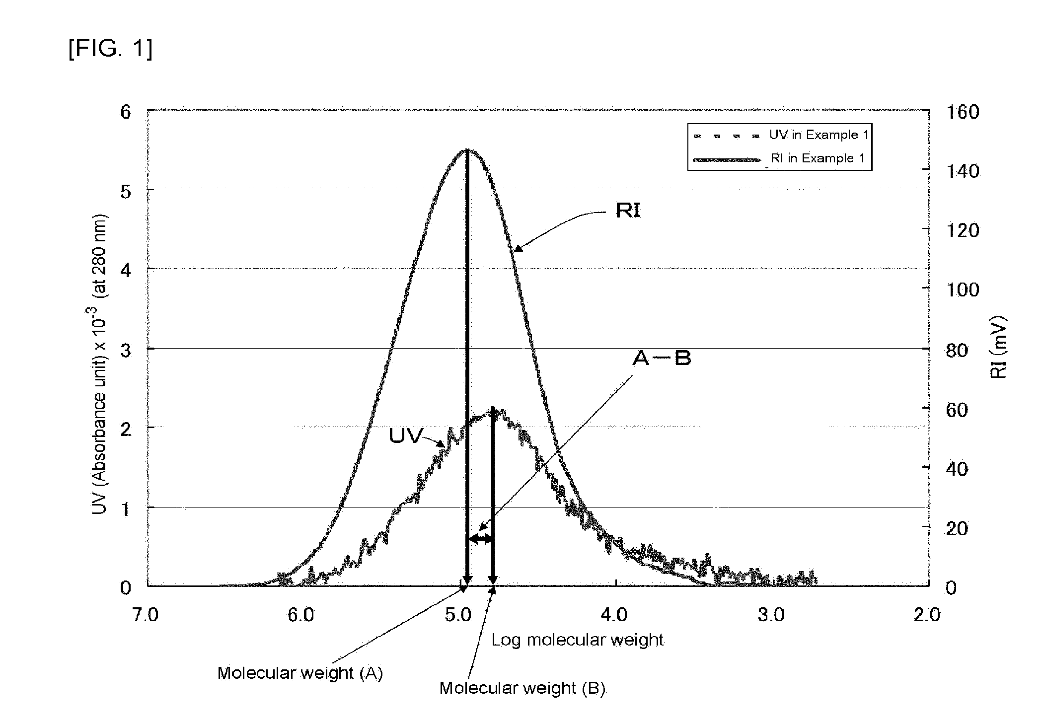
There is provided a binder for ceramic formation or a conductive paste, comprising polyvinyl acetal having a degree of acetalization of from 50 to 85 mol %, a content of vinyl ester monomer unit of from 0.1 to 20 mol %, and having a viscosity-average degree of polymerization of from 200 to 5000, wherein a peak-top molecular weight (A) as measured by a differential refractive index detector and a peak-top molecular weight (B) as measured by an absorptiometer (measurement wavelength: 280 nm) in gel permeation chromatographic measurement of the polyvinyl acetal heated at 230° C. for 3 hours satisfy a formula (1) (A−B) / A<0.60 and the polyvinyl acetal has an absorbance in the peak-top molecular weight (B) of from 0.50×10⁻³ to 1.00×10⁻².

Description

TECHNICAL FIELD[0001]The present invention relates to a binder for ceramic formation containing polyvinyl acetal. The present invention also relates to a binder for a conductive paste containing polyvinyl alcohol. The present invention further relates to uses thereof.BACKGROUND ART[0002]Polyvinyl acetal is produced by acetalization reaction of a polyvinyl alcohol (hereinafter, sometimes abbreviated as “PVA”) and aldehyde compound in water under acidic conditions. Since polyvinyl acetal is used to produce a tough film and has a unique structure where it has both hydrophilic hydroxyl groups and hydrophobic acetal groups, a variety of polymers have been proposed. Among them, a polyvinyl formal produced from PVA and formaldehyde, a polyvinyl acetoacetal produced from PVA and acetaldehyde, and polyvinyl butyral produced from PVA and butyraldehyde are commercially important.[0003]In particular, polyvinyl butyral has been widely used as a binder for ceramic formation, various binders and f...

Claims


Application Information

Patent Timeline
IPC IPC(8): C08F216/38C04B35/634C09D5/24C04B41/80C08F18/08C08F16/06C04B41/00H01B1/22C08K3/08
CPCC08F216/38H01B1/22C04B35/6342C09D5/24C08K3/08C08F18/08C08K2201/001C04B41/0054C04B41/80C04B41/009C08F2800/20C08K2003/0862C08F2500/17C08F16/06C04B35/4682C04B35/634C08F8/12C08F8/28C08F16/38C08F218/08C08F2800/10C08F118/08C08F216/06B28B11/04C08L29/14
Inventor KUSUDOU, TAKESHIASANUMA, YOSHIAKITOKUCHI, KAZUKISHIMAZUMI, YUHI
Owner KURARAY CO LTD
Why Eureka
Try Eureka