Spherical fusion reactor with aerogel material

a fusion reactor and aerogel technology, applied in nuclear reactors, nuclear engineering, greenhouse gas reduction, etc., can solve the problems of large technical challenges, physical damage to the machine, and the reactors can operate with so much plasma that the reactors cannot be fusioned, so as to facilitate the breakdown of fusion fuel and resist flow.

Inactive Publication Date: 2017-01-26
GIBSON RICHARD ALLEN
View PDF0 Cites 7 Cited by
  • Summary
  • Abstract
  • Description
  • Claims
  • Application Information

AI Technical Summary

Benefits of technology

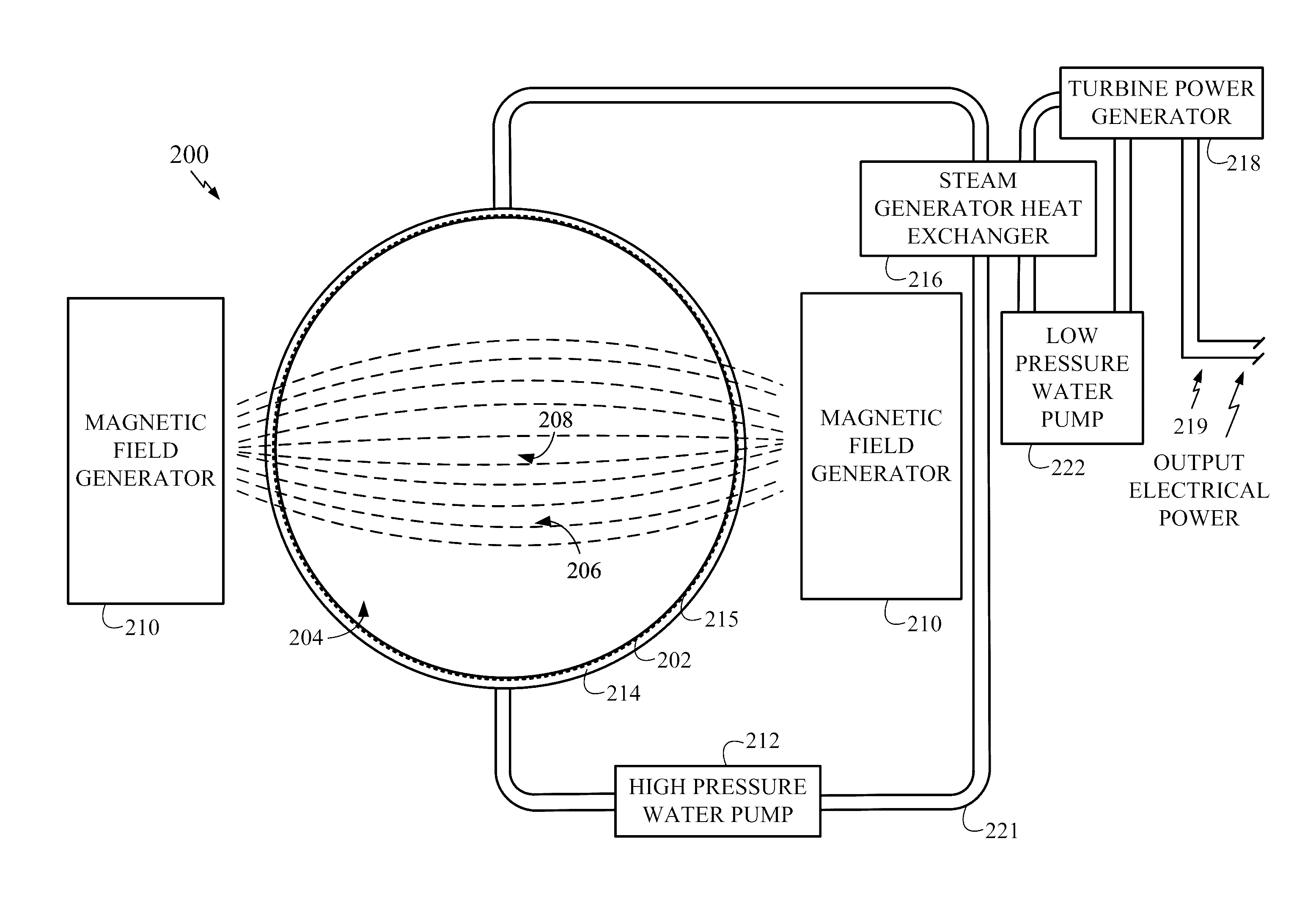
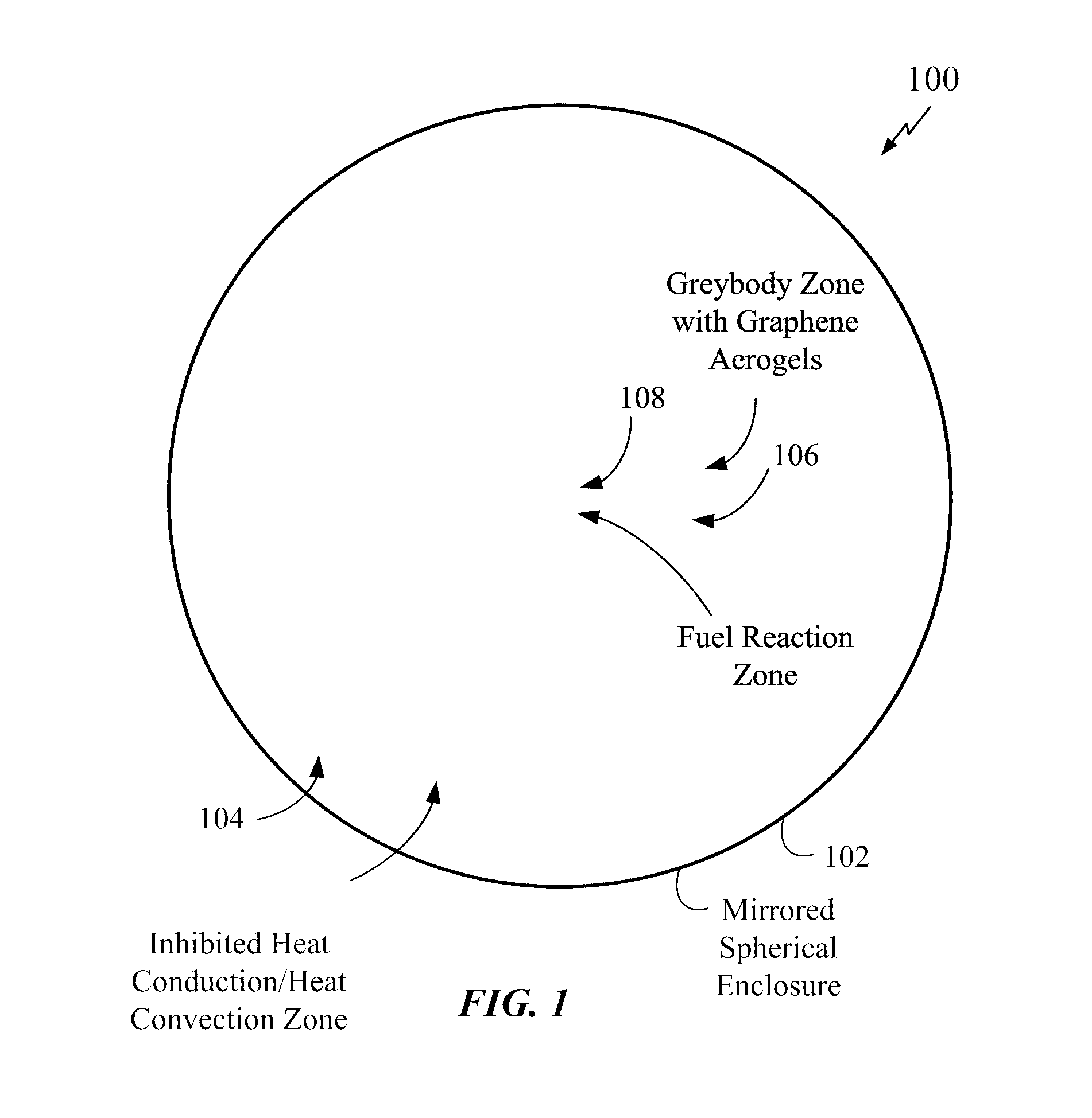
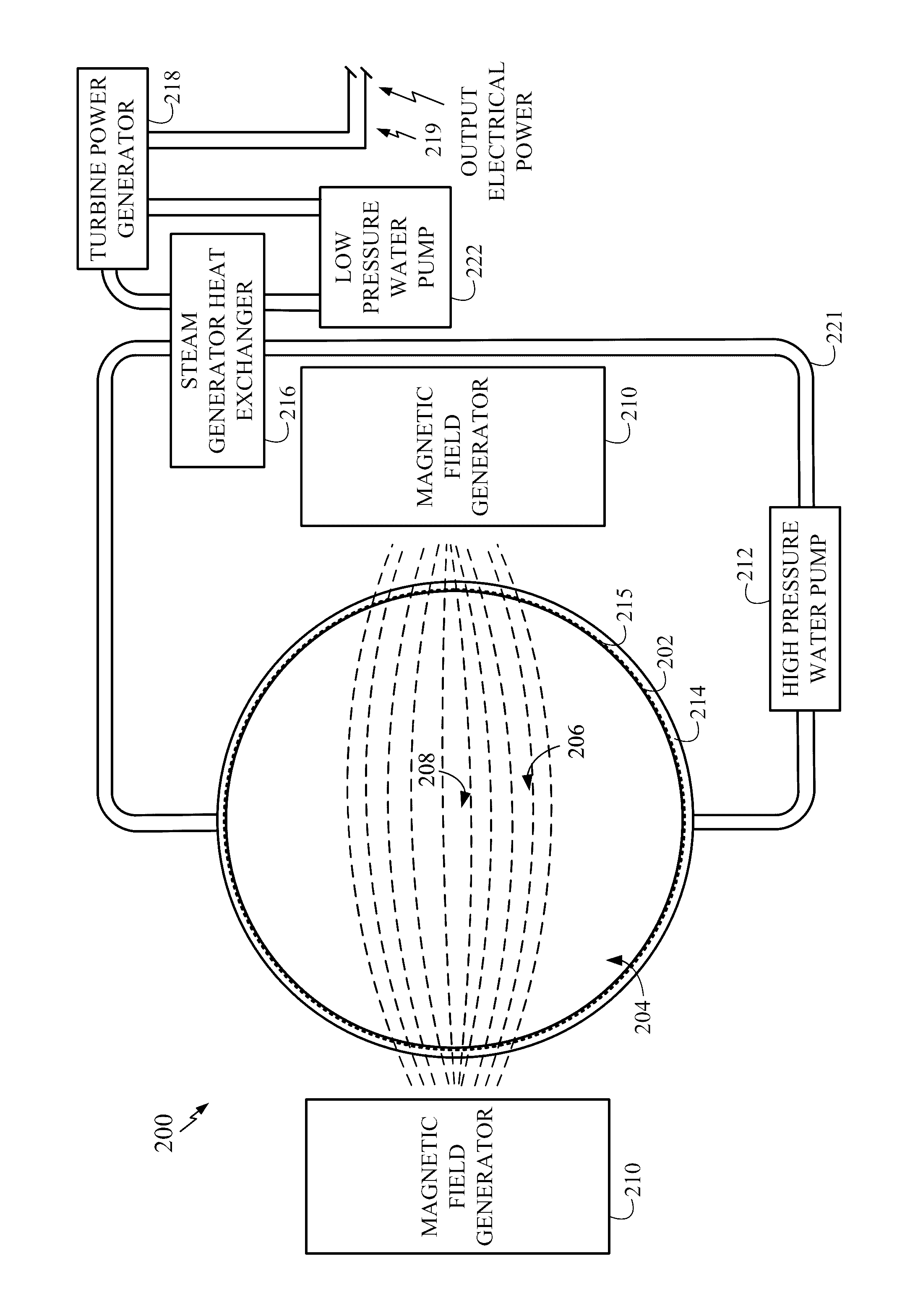
[0008]In an exemplary embodiment, a nuclear fusion reactor apparatus, device or machine includes: a fuel reaction zone and a graphene aerogel material enclosing at least a portion of the fuel reaction zone. In an illustrative embodiment, the graphene aerogel material acts as a greybody and is adapted to function as a radiation frequency converter and a thermal capacitor, which stores sufficient energy (in, e.g., multiple machines) to provide the electrical output power of the plant. The graphene aerogel material can be at least partially infused with a heavy noble gas (HNG) such as xenon, krypton or argon or combinations thereof. In the illustrative embodiment, the graphene aerogel material has high resistance to the flow of heat via thermal conductance and thermal convection and substantially absorbs the intermittent high frequency electromagnetic radiation produced in the fuel reaction zone while fusion reactions are occurring and converts it to a continuous stream of low frequency electromagnetic radiation with a spectral radiance curve that is similar to that produced by the sun. A substantially spherical enclosure can be provided with an inn

Problems solved by technology

At present, such devices typically operate for only several milliseconds before plasma instabilities cause the heated fusion fuel to escape the magnetic field.
Fusion has been achieved in such devices but instabilities in the plasma often render the plasma so unstable the reactors can operate only for short periods of time (e.g. milliseconds).
Moreover, unstable operation in such devices can produce very energetic electrons (i.e. runaway electrons) that can physically damage the machine.
However, to make Inertial Confinement fusion practi

Method used


Image

  • Spherical fusion reactor with aerogel material
  • Spherical fusion reactor with aerogel material
  • Spherical fusion reactor with aerogel material

Examples


Embodiment Construction

[0028]In the following descriptions, specific details are given to provide a thorough understanding of the various aspects of the disclosure. However, it will be understood by one of ordinary skill in the art that the aspects may be practiced without these specific details. The word “exemplary” is used herein to mean serving as an example, instance, or illustration. Any implementation or aspect described herein as “exemplary” is not necessarily to be construed as preferred or advantageous over other aspects of the disclosure. Likewise, the term “aspects” does not require that all aspects of the disclosure include the discussed feature, advantage or mode of operation.

Overview of Exemplary Nuclear Fusion Reactor Apparatus, Device or Machine

[0029]Aspects of the nuclear fusion reactor described herein exploit graphene. Graphene and its derivatives such as graphene aerogels are used herein to provide fusion-powered plants producing electricity using otherwise conventional steam powered t...


PUM


Abstract

A spherical nuclear fusion reactor machine is provided that uses a graphene aerogel material to enclose a fuel reaction zone. In illustrative examples described herein, the graphene aerogel material functions as a greybody material and includes a heavy noble gas such as xenon, krypton or argon or combinations thereof. The fuel reaction zone includes a radioactive isotope such as polonium-210 in addition to fusion fuel. A component of the heavy noble gas may be a radioactive isotope of xenon, Xe-135. A spherical enclosure with a reflective inner surface surrounds the fuel reaction zone and the graphene aerogel material. Magnetic field generators with rotating permanent magnets or electro-magnets and fixed electro-magnets are also provided. The magnetic field generators are external to the spherical enclosure and are configured to produce magnetic fields within the fuel reaction zone to initiate nuclear fusion and to generate a magnetic “bottle” to contain the fusion materials.

Description

BACKGROUND[0001]Field of the Invention[0002]Aspects of the invention relate to nuclear fusion reactors and, in particular, to fusion reactors employing the magnetic bottle effect.[0003]Description of Related Art[0004]Nuclear fusion reactors are devices that operate to generate energy by exploiting nuclear fusion reactions. Examples include Magnetic Confinement Machines that use magnetic fields to confine and energize a plasma (i.e. an ultra-high temperature, ionized gas). At present, such devices typically operate for only several milliseconds before plasma instabilities cause the heated fusion fuel to escape the magnetic field. Other examples of fusion reactors include Z-Pinch Machines where a magnetic pinch (i.e. a Z-pinch) creates the high fuel temperatures needed for fusion reactions. Z-Pinch Machines exploit the Lorentz force in which a current-carrying conductor in a magnetic field experiences a force. When an electrical current passes through the plasma, particles in the plas...

Claims


Application Information

Patent Timeline
IPC IPC(8): G21B1/13G21B1/17G21B1/05
CPCG21B1/13G21B1/17G21B1/05H05H1/10Y02E30/10
Inventor GIBSON, RICHARD ALLEN
Owner GIBSON RICHARD ALLEN
Why Eureka
Try Eureka