
Brushless Motor and System Thereof

Inactive Publication Date: 2017-02-16
FOSTER ASSETS CORPORATION
View PDF4 Cites 9 Cited by
  • Summary
  • Abstract
  • Description
  • Claims
  • Application Information

AI Technical Summary

Benefits of technology

The present invention is an electric motor with permanent magnets positioned in the rotor. The advantages include a reduction or elimination of the risk of permanent magnet detachment, improved energy conversion efficiency, and increased performance. The rotor also includes grooves that create air flow to dissipate heat accumulated in the motor. The motor system has multiple structures, such as separate controllers for coils and motors, which allows for flexible power output and energy-saving. These features make the motor system more efficient, effective, and adaptable.

Problems solved by technology

However, there are also some drawbacks associated with existing brushless motors, one of which is that controllers for high power brushless motor, such as that used in electrically driven vehicle or hybrid electric-petroleum vehicles, are difficult to manufacture, due to the reason that the controller has to bear a large current which is required for generating high power output from the motor.
Consequently, the manufacturing complexity for making a controller with high-power components results in high costs which is not desirable.
In addition, failure or malfunctioning of the controller leads to interruption of the operation of the whole brushless motor with no backup option.

Method used


Image

  • Brushless Motor and System Thereof
  • Brushless Motor and System Thereof
  • Brushless Motor and System Thereof

Examples


Embodiment Construction

[0028]In the claims which follow and in the preceding description of the invention, except where the context requires otherwise due to express language or necessary implication, the word “comprise” or variations such as “comprises” or “comprising” is used in an inclusive sense, i.e. to specify the presence of the stated features but not to preclude the presence or addition of further features in various embodiments of the invention.

[0029]As used herein and in the claims, “couple” or “connect” refers to electrical coupling or connection either directly or indirectly via one or more electrical means unless otherwise stated.

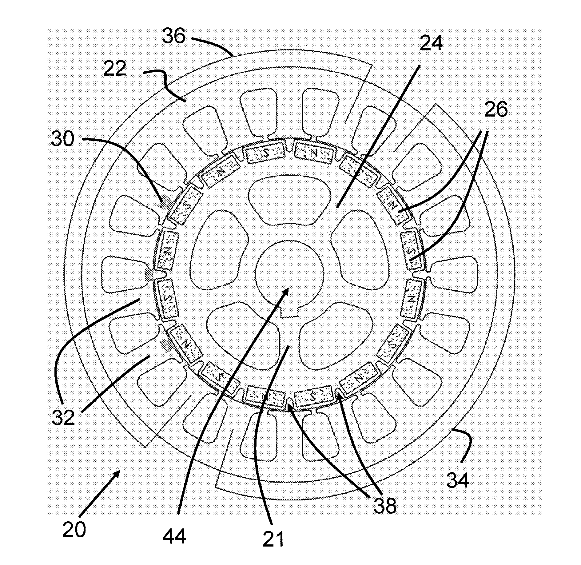
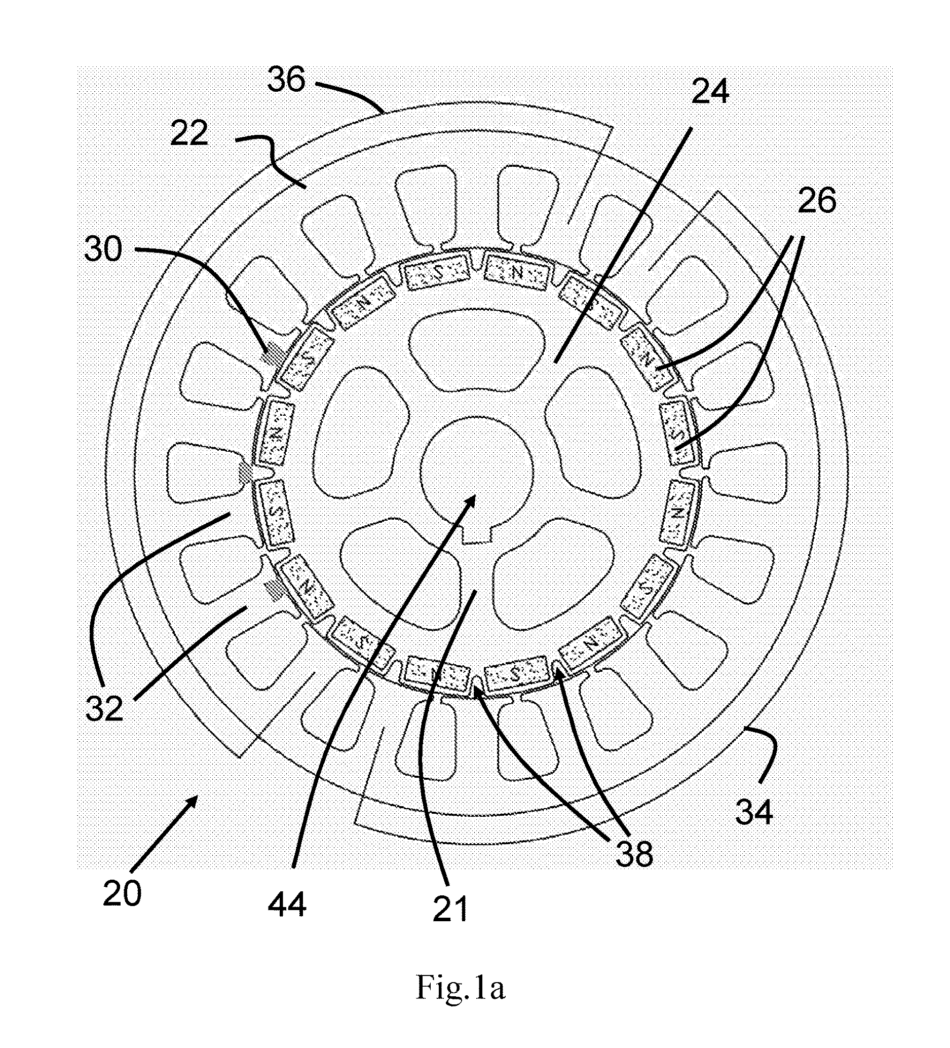
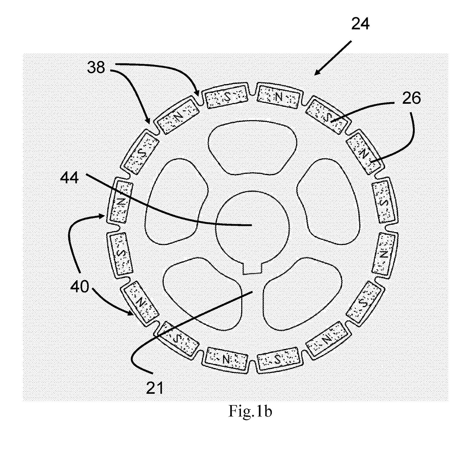
[0030]Referring now to FIGS. 1a, 1b and 2, the first embodiment of the present invention is a brushless motor which consists of a stator 22 and a rotor 24. The core 21 of the rotor 24 is preferably manufactured by stacking multiple silicon steels, and the rotor core 21 has a hollow shape through which a shaft 44 is mounted. As shown in FIG. 2, the shaft 44 is rotata...


PUM


Abstract

A brushless motor controller system includes a brushless motor (201) which further contains a rotor (24) and a stator (22), a plurality of independent motor controllers (203), a plurality of batteries (204), and a plurality of battery chargers (205). The stator (22) of the brushless motor (201) has a plurality of salient poles (32). A plurality of coils are wound on the salient poles (32) such that on each of the salient poles (32) there is wound different groups of windings electrically isolated from each other. The plurality of independent motor controllers (203) each corresponds and is electrically connected to one of the groups of windings on one of the salient poles (32) of the brushless motor (201). The plurality of batteries (204) each is connected to a corresponding one of the independent motor controllers (203) to provide electrical power thereto. The plurality of battery chargers (205) each is connected to el a corresponding one of the batteries (204). The plurality of independent motor controllers (203) each is adapted to power and control a corresponding one of the groups of coils on one of the salient poles (32) in the brushless motor (201) independently. The brushless motor controller system utilizes distributed motor controllers (203), batteries (204) and chargers (205) for brushless DC motor (201) which provides not only flexibility in motor output control but also redundancies of the controlling system making it more robust.

Description

TECHNICAL FIELD This invention relates to a brushless motor and a system thereof, in particular a brushless motor with flexible output power.BACKGROUND ART[0001]Permanent magnet brushless motors have been widely used in various electrical applications such as three-phase pumps, fans, blowers, compressors, conveyor drives, etc. The drive power of the brushless motor is provided by the cutting effect of the permanent magnetic field from the permanent magnet and the variable electromagnetic field generated by coils or so called windings in the brushless motors. Compared to brushed motors, brushless motors as they contain no brush / commutator assembly provides higher efficiency, and reliability due to elimination of ionizing sparks from the commutators, A magnetic sensitive Hall effect component is installed in some brushless motors to collect signals of the permanent magnetic field, which are used as a reference for controlling the electrical power supplied to the windings of the motor....

Claims


Application Information

Patent Timeline
IPC IPC(8): H02K21/12H02K11/215H02K11/33H02J7/00H02K1/08H02K3/18
CPCH02K21/12H02K1/08H02K11/215H02K11/33H02J7/0013H02K3/18H02K3/28H02K16/04H02K2213/06H02K2213/12
Inventor CHAN, YET
Owner FOSTER ASSETS CORPORATION
Features
  • Generate Ideas
  • Intellectual Property
  • Life Sciences
  • Materials
  • Tech Scout
  • Unparalleled Data Quality
  • Higher Quality Content
  • 60% Fewer Hallucinations
Learn More