

Dielectric material and electrostatic chucking device
- Summary
- Abstract
- Description
- Claims
- Application Information
AI Technical Summary
Benefits of technology
Problems solved by technology
Method used
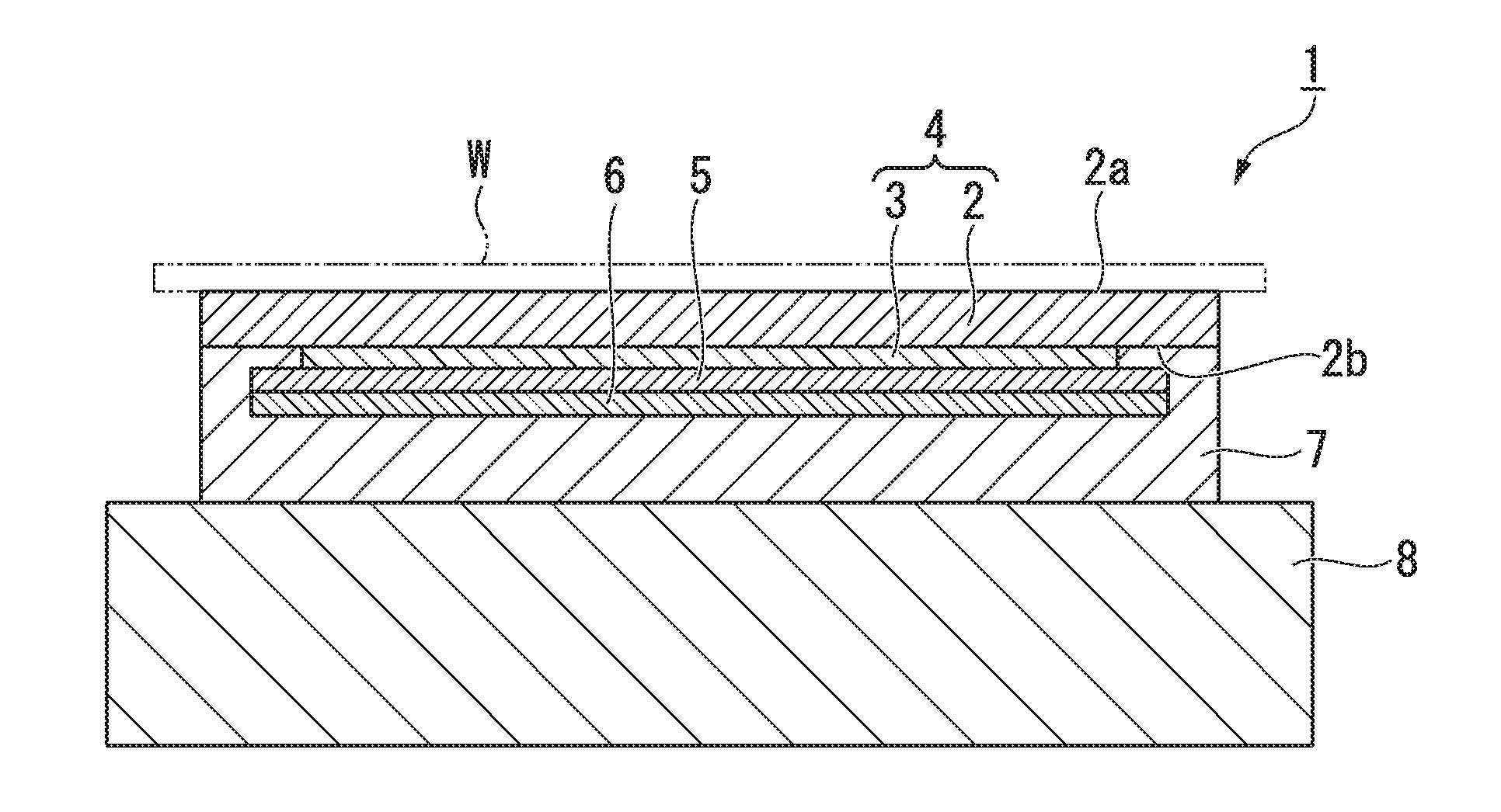
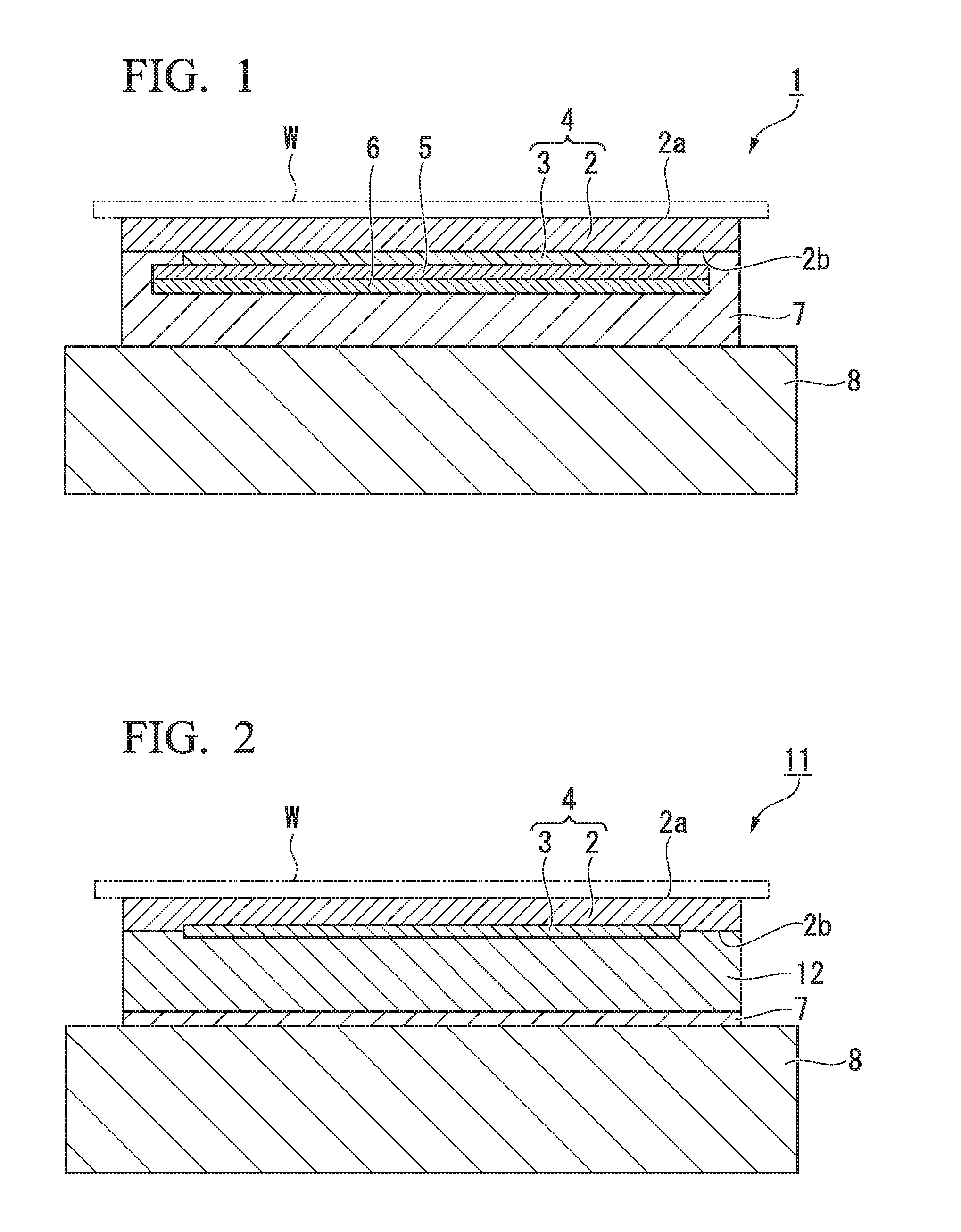
Image

Examples
example 1
[0170]A silicon carbide (SiC) powder having an average particle diameter of 0.03 μm, a silicon carbide (SiC) powder having an average particle diameter of 0.05 μm, a silicon carbide (SiC) powder having an average particle diameter of 0.1 μm are mixed with each other at a mass ratio of 1:1:1 to obtain mixed silicon carbide (SiC) powder.
[0171]Next, 8% by mass of the mixed silicon carbide (SiC) powder and 92% by mass of an aluminum oxide (Al2O3) powder having an average particle diameter of 0.1 μm were weighed, 72 parts by mass of water was added thereto with respect to 100 parts by mass of the total mass of the powders, and the components were stirred. As a result, a slurry was obtained.
[0172]Next, this slurry was put into a wet jet mill (HJP-25010, manufactured by Sugino Machine Ltd.) and was compressed under a pressure of 150 MPa such that particles of the slurry collide against each other in an oblique direction. As a result, the components were dispersed for 120 minutes, and a dis...
example 2
[0176]A dielectric plate formed of the Al2O3—SiC composite sintered body according to Example 2 was prepared using the same method as in Example 1, except that 11% by mass of the mixed silicon carbide (SiC) powder and 89% by mass of an aluminum oxide (Al2O3) powder were weighed.
example 3
[0177]A dielectric plate formed of the Al2O3—SiC composite sintered body according to Example 3 was prepared using the same method as in Example 1, except that 9% by mass of the mixed silicon carbide (SiC) powder and 91% by mass of an aluminum oxide (Al2O3) powder were weighed.
PUM
| Property | Measurement | Unit |
|---|---|---|
| Temperature | aaaaa | aaaaa |
| Temperature | aaaaa | aaaaa |
| Percent by mass | aaaaa | aaaaa |
Abstract
Description
Claims
Application Information