Ultra-small cavity with reflecting metasurfaces

a metasurface and ultra-small technology, applied in the field of ultra-small cavities, can solve the problems of difficult coupling waves to and from spp cavities, difficult to integrate them efficiently with external devices, and complicated techniques for using negative permittivity and permeability

Inactive Publication Date: 2017-03-23
PURDUE RES FOUND INC
View PDF0 Cites 17 Cited by
  • Summary
  • Abstract
  • Description
  • Claims
  • Application Information

AI Technical Summary

Benefits of technology

[0010]Employment of a reflecting metasurface based on plasmonic nanostructure elements changes the cavity resonance condition that currently causes restrictions on minimum length. This also does not occur at the expense of light confinement inside the cavity because plasmon elements couple electromagnetic waves into free electron plasma. Hence, the localized energy not only exists in the form of electromagnetic energy but also exists in the form of mechanical energy of oscillating electrons over very short-length scales near the metasurface. Physically speaking, the short length of wave propagation between the cavity walls is compensated by strong localization of electromechanical energy near the metasurface walls, which experience considerable phase shifts over a very small distance. All energy forms remain highly confined between the cavity walls.

Problems solved by technology

The technique of using negative permittivity and permeability is complicated in practice, e.g., to build a bulk meta-material with such properties, and it would include losses due to a large amount of metal used in the meta-material.
Photonic crystal cavities can provide very high Quality factors (Q), but their size is limited by the wavelength order and they do not reach deep sub-wavelength.
Cavities operating on surface plasmon polariton (SPP) waves can reach very small sizes, but SPP waves have resonant modes that are dissimilar to modes existing in conventional optic devices, making it harder to couple waves to and from SPP cavities, or to integrate them efficiently with external devices.
Solutions provided using meta-films embedded between dielectric layers have limited effects of reducing the size of the cavity by a factor of only 2 or 3.
For example, using metals with high losses as mirrors can result in a reflecting phase shift different from IC due to a significant portion of the wave penetrating through the metal during reflection.
Such a structure can have a distance between mirrors of less than λ / 2 but the mode will not truly be confined between minors, as part of the mode will penetrate the metal, causing high losses and a very unreliable quality factor.

Method used


Image

  • Ultra-small cavity with reflecting metasurfaces
  • Ultra-small cavity with reflecting metasurfaces
  • Ultra-small cavity with reflecting metasurfaces

Examples


Embodiment Construction

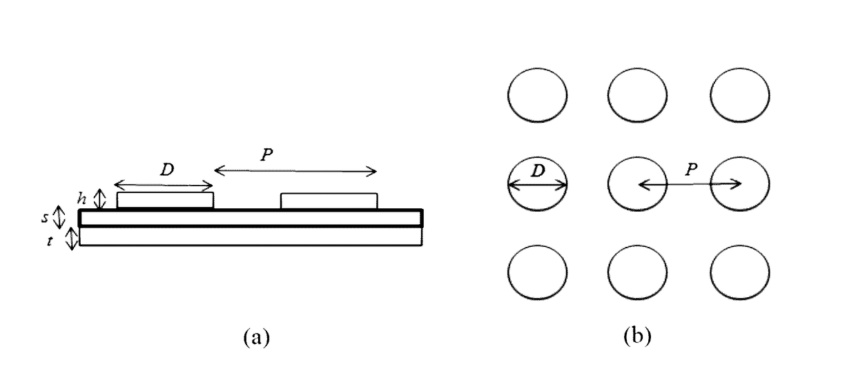
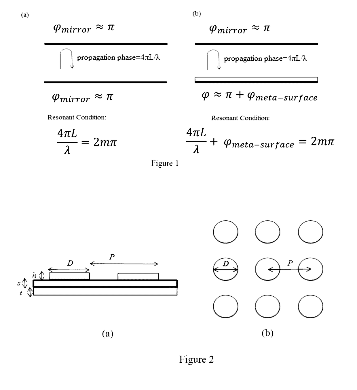
[0022]The abstract design of the invention is illustrated by FIG. 1, which shows a comparison between a conventional parallel mirror Fabry-Pérot resonator (FIG. 1(a)) and the currently disclosed structure, where one or both mirrors are coupled to a metasurface (FIG. 1(b)), adding an arbitrary phase shift of φmeta-surface. In the conventional case, the resonance condition is 4πL / λ=2mλ, imposing a minimum limit of λ / 2 on the value of L. With the present invention structure, however, the resonance condition becomes 4πL / λ+φmeta-surface=2mπ. With the fact that φmeta-surface can be designed to take on any value from 0 to 2 π, the effect is no constraint on L, allowing L to be arbitrarily small. Although fabrication techniques might currently place constraints on size, there are no fundamental physical size constraints on the present invention. The fabrication and use of smaller-scale devices such as those described herein are more useful and more applicable because they are highly integra...


PUM


Abstract

The present invention provides a new approach for subwavelength cavity solutions. Employment of a reflecting metasurface based on plasmonic nanostructure elements changes the cavity resonance condition that currently causes restrictions on minimum length. The short length of wave propagation between the cavity walls is compensated by strong localization of electromechanical energy near the metasurface walls, which experience considerable phase shifts over a very small distance. Subwavelength 2D and 3D cavities find implementation as laser sources, optical parametric oscillators, interferometers, laser phase and frequency stabilizers, laser spatial and temporal filters, adaptive beam, and pulse shaping devices.

Description

CROSS-REFERENCE TO RELATED APPLICATIONS[0001]This patent application claims priority to U.S. provisional application No. 61 / 933,342 filed on Jan. 30, 2014, which fully incorporated herein by reference.STATEMENT REGARDING FEDERALLY SPONSORED RESEARCH AND DEVELOPMENT AND GOVERNMENT RIGHTS[0002]This invention was made with government support under FA9550-12-1-0024 awarded by United States Air Force. The government has certain rights in the invention.FIELD OF THE INVENTION[0003]The claimed invention of ultra-small cavity via placing phase-fitting metasurfaces coupled to cavity mirrors, relates to the field of nanophotonics, impacting areas including, but not limited to, nanolasers, threshold-less lasing, applications resulting from the Purcell effect, e.g., spontaneous emission enhancement, single photon sources, quantum computation devices, and nanometer scale cavity-based optical devices such as optical parametric oscillators, interferometers, laser phase and frequency stabilizers, la...

Claims


Application Information

Patent Timeline
Patent Type & Authority Applications(United States)
IPC IPC(8): G02B17/00H01S5/10H01S5/06G02B5/00
CPCG02B17/004H01S5/0607H01S5/1042G02B5/008H01S5/1046
Inventor SHALTOUT, AMR MOHAMMAD E. A.KILDISHEV, ALEXANDER V.SHALAEV, VLADIMIR M.
Owner PURDUE RES FOUND INC
Why Eureka
Try Eureka