
Device and Method for Non-Invasive Measuring of Analytes

a non-invasive and analyte technology, applied in the direction of optical radiation measurement, diagnostics using spectroscopy, instruments, etc., can solve the problems of limiting the applicability of the raman technique to routine non-invasive measurements, time-consuming and cumbersome process, and difficulty in quantifying the concentration of a particular analyte, etc., to achieve the effect of fast measurement of an analy

Active Publication Date: 2017-04-13
INTERUNIVERSITAIR MICRO ELECTRONICS CENT (IMEC VZW)
View PDF14 Cites 16 Cited by
  • Summary
  • Abstract
  • Description
  • Claims
  • Application Information

AI Technical Summary

Benefits of technology

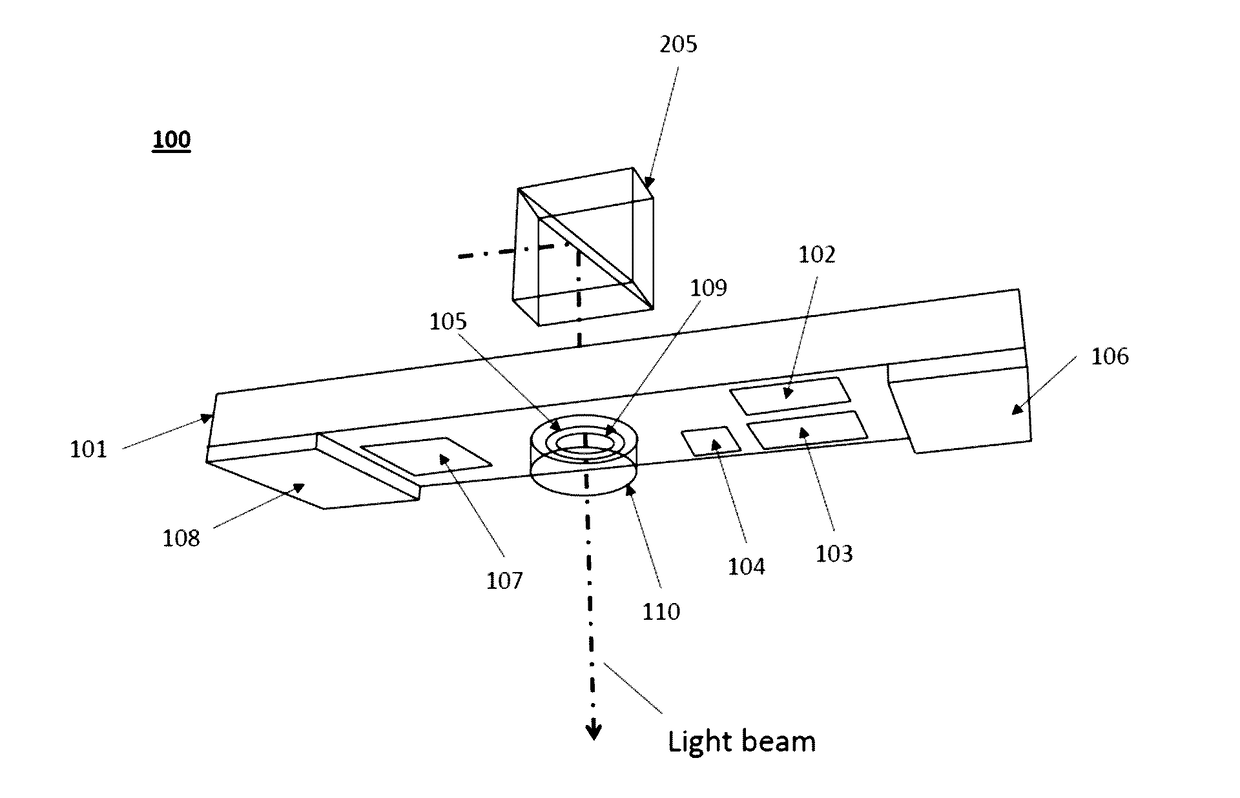
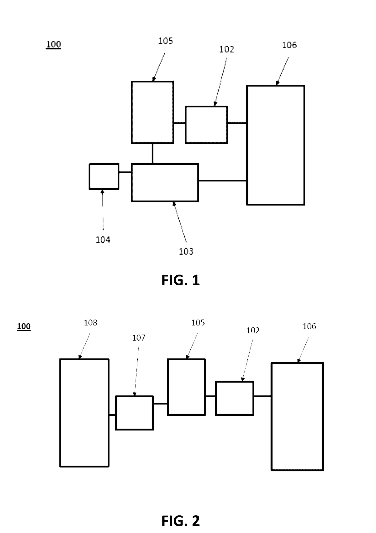
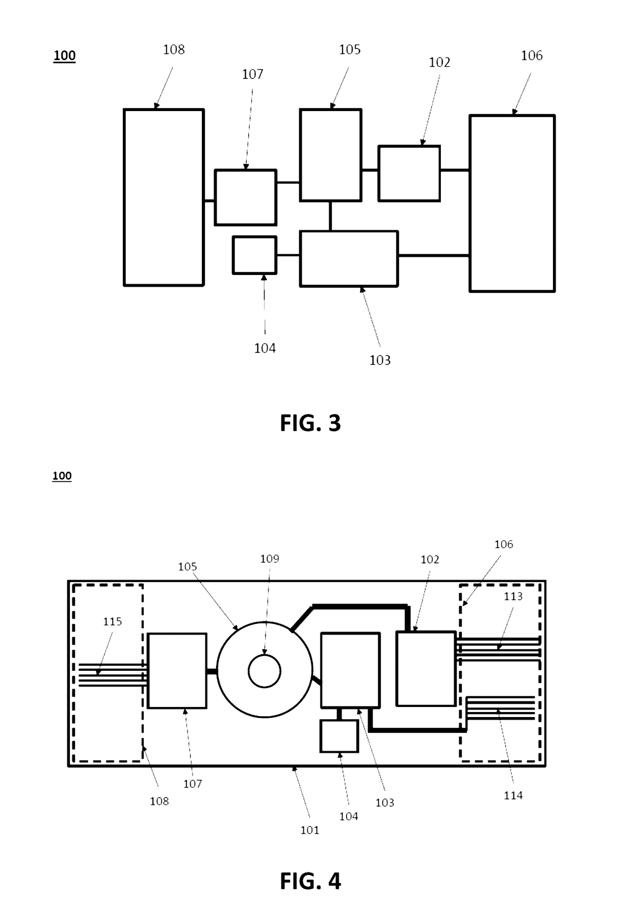
The present invention relates to a wearable system for non-invasive measuring of the concentration of an analyte in skin tissue. The system includes an integrated circuit with a RAMAN spectrometer, an OCT spectrometer, an interferometer and a light coupler for analyzing scattered and reflected light from the tissue. The system also includes a laser beam for performing Raman spectroscopy and a broadband light beam for performing OCT or IR spectroscopy. The device is compact, affordable, and can provide fast and reliable measurements of analytes in complex living tissue.

Problems solved by technology

However, due to the differences in the local geometry of the skin (e.g. different thicknesses and microstructure of the various layers that make up skin) it is difficult to quantify the concentration of a particular analyte without performing calibration steps for each individual separately.
This is a time consuming and cumbersome process that limits the applicability of the Raman technique to do routine non-invasive measurements of important analytes such as glucose, cholesterol, ethanol, etc.
A first disadvantage of the described device is the size of the device which makes it unsuitable for use in wearable applications.
A second disadvantage is the high cost of the device due to the use of microscopes.
As a third disadvantage, the device cannot be used to perform measurements at multiple locations of a sample at the same time.
This makes the device less suitable for performing measurements on living tissue.

Method used


Image

  • Device and Method for Non-Invasive Measuring of Analytes
  • Device and Method for Non-Invasive Measuring of Analytes
  • Device and Method for Non-Invasive Measuring of Analytes

Examples


example

[0106]When the integrated circuit comprises three active electric component layers, each layer comprising an optical unit, the light coupler of the first layer may be configured to couple light with a wavelength of 820-850 nm into the RAMAN spectrometer of the optical unit of the first layer. The light coupler of the second layer may be configured to couple light with a wavelength of 850-880 nm into the RAMAN spectrometer of the optical unit of the second layer. The light coupler of the third layer may be configured to couple light with a wavelength of 880-910 nm into the RAMAN spectrometer of the optical unit of the third layer. In this configuration, the integrated circuit is capable of receiving and spectrally resolving RAMAN scattered light with a wavelength of 820-910 nm. In this example, the wavelength ranges of different light couplers are adjacent to extend the wavelength range of the integrated circuit.

[0107]To separate different active electronic component layers from each...


PUM


Abstract

The present disclosure relates to devices and methods for non-invasive measuring of analytes. At least one embodiment relates to a wearable system for non-invasive measuring of a concentration of an analyte in skin tissue. The wearable system includes an integrated circuit that includes a first optical unit. The first optical unit includes a Raman spectrometer. The first optical unit also includes an OCT spectrometer and an interferometer optically coupled to the OCT spectrometer or an infrared (IR) spectrometer. The first optical unit additionally includes a light coupler. The wearable system further includes a first light source for performing Raman spectroscopy. The wearable system additionally includes a second light source for performing OCT spectroscopy or IR spectroscopy. Still further, the wearable system includes read-out electronics to determine an optical model of the skin tissue based on the spectroscopic data and to determine the concentration of the analyte.

Description

FIELD OF THE INVENTION[0001]The disclosure relates to techniques for non-invasive measuring of analytes. In particular, the disclosure relates to techniques for non-invasive measuring of analytes in skin tissue using Raman spectroscopy and at least one of optical coherence tomography measurements and infrared measurements.BACKGROUND OF THE INVENTION[0002]Raman spectroscopy is a known technique for identifying molecules. The identification is based on vibrational information specific to chemical bonds and symmetry of molecules. The technique provides a fingerprint by which molecules may be identified. Raman spectroscopy can also be used to identify molecules in the skin of an individual and to estimate the total number of such molecules in the volume probed by the Raman measurement. However, due to the differences in the local geometry of the skin (e.g. different thicknesses and microstructure of the various layers that make up skin) it is difficult to quantify the concentration of a...

Claims


Application Information

Patent Timeline
Patent Type & Authority Applications(United States)
IPC IPC(8): A61B5/1455A61B5/145A61B5/00
CPCA61B5/1455A61B5/0075A61B5/0066A61B5/1451A61B5/681A61B2562/0233G01N21/65G01B9/02091G01N21/35G01N2201/12A61B5/14532A61B5/443G01J3/0256G01J3/44G01N2201/0633G01N2201/0636G01J3/0291
Inventor VAN DORPE, POLPEUMANS, PETER
Owner INTERUNIVERSITAIR MICRO ELECTRONICS CENT (IMEC VZW)
Learn More