

Multi-stage resistance spot welding method for workpiece stack-up having adjacent steel and aluminum workpieces
- Summary
- Abstract
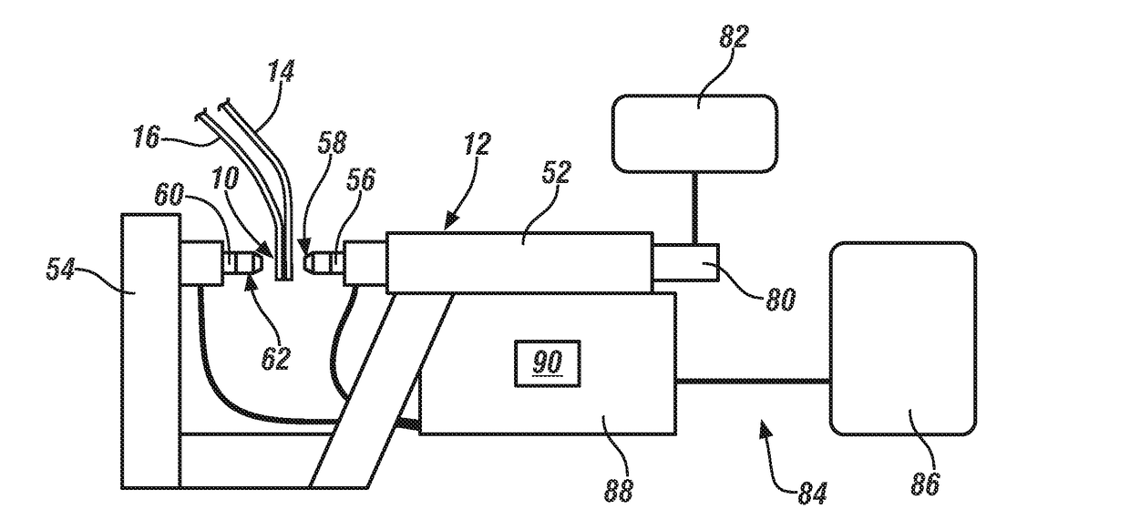
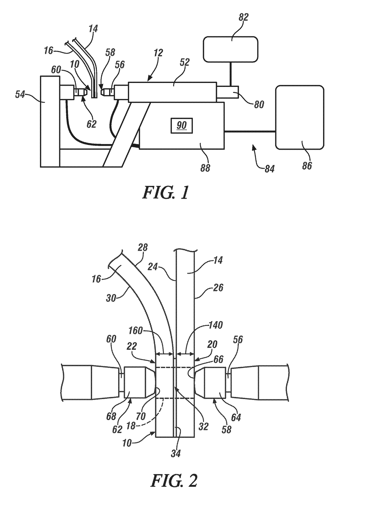
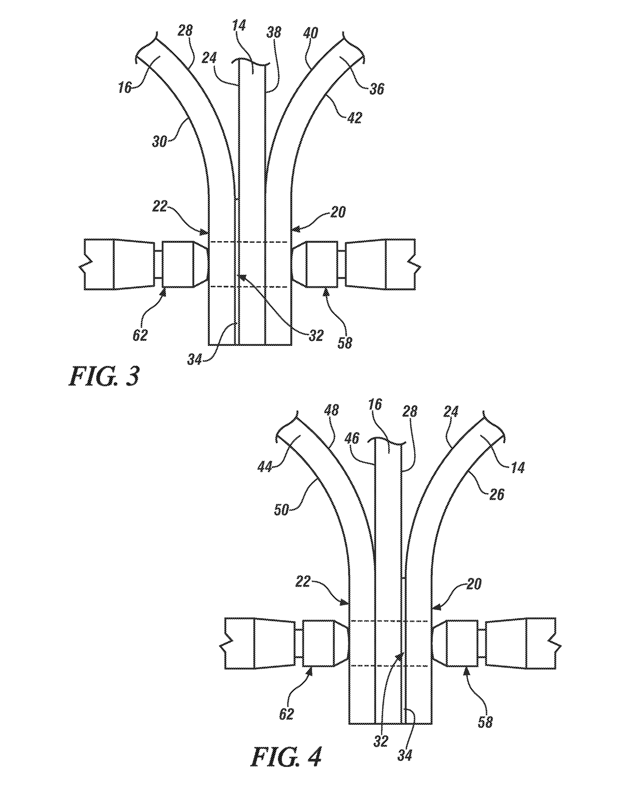
- Description
- Claims
- Application Information
AI Technical Summary
Benefits of technology
Problems solved by technology
Method used
Image

Examples
example 1
[0074]In this example, which corresponds to FIG. 13, a 0.8-mm thick X626-T4 aluminum alloy workpiece was spot welded to a 0.9-mm thick hot-dip galvanized steel workpiece by the multi-stage spot welding method under 800 lb of force applied by the spot welding electrodes until the conclusion of the last weld joint refining stage. Here, in the weld joint origination stage, as shown, electrical current was passed through the workpieces at a constant current level of 19 kA for a first period of 50 ms to create a molten aluminum weld pool within the aluminum workpiece. Passage of electrical current was then ceased for a second period of 50 ms to solidify the molten aluminum weld pool into a weld joint. Next, six weld joint refining stages were executed. For each weld joint refining stage, the current level and magnitude of the electrical current passed between the electrodes to cause remelting, and the extent and duration to which the current level of the electrical current was dropped to...
example 2
[0075]In this example, which corresponds to FIG. 14, a 0.8-mm thick X626-T4 aluminum alloy workpiece was spot welded to a 0.9-mm thick hot-dip galvanized steel workpiece by the multi-stage spot welding method under 800 lb of force applied by the spot welding electrodes until the conclusion of the last weld joint refining stage. Here, in the weld joint origination stage, as shown, electrical current was passed through the workpieces at a current level that increased linearly from 18.02 kA to 18.25 kA over a first period of 50 ms to create a molten aluminum weld pool within the aluminum workpiece. Passage of electrical current was then ceased for a second period of 50 ms to solidify the molten aluminum weld pool into a weld joint. Next, seven weld joint refining stages were executed. For each weld joint refining stage, the current level and magnitude of the electrical current passed between the electrodes to cause remelting, and the extent and duration to which the current level of th...
example 3
[0076]In this example, which corresponds to FIG. 15, a 0.8-mm thick X626-T4 aluminum alloy workpiece was spot welded to a 1.2-mm thick hot-dip galvanized steel workpiece by the multi-stage spot welding method under 800 lb of force applied by the spot welding electrodes until the conclusion of the last weld joint refining stage. Here, in the weld joint origination stage, as shown, electrical current was passed through the workpieces at a current level that increased linearly from 14.02 kA to 14.6 kA over a first period of 100 ms to create a molten aluminum weld pool within the aluminum workpiece. Passage of electrical current was then ceased for a second period of 100 ms to solidify the molten aluminum weld pool into a weld joint. Next, four weld joint refining stages were executed. For each weld joint refining stage, the current level and magnitude of the electrical current passed between the electrodes to cause remelting, and the extent and duration to which the current level of th...
PUM
| Property | Measurement | Unit |
|---|---|---|
| Fraction | aaaaa | aaaaa |
| Time | aaaaa | aaaaa |
| Time | aaaaa | aaaaa |
Abstract
Description
Claims
Application Information