
Differential current mode analog front-end circuit for capacitive touch sensing in touchscreen panels

a capacitive touch and capacitive technology, applied in the field of capacitive touch sensing circuitry of capacitive touchscreen, can solve the problems of limited /sub>out/sub>, distortion of screen electrostatic field, limited voltage headroom of output voltage, etc., to improve common mode noise rejection, improve snr, and improve the effect of parallel differential sensing efficiency

Active Publication Date: 2017-05-04
SOLOMON SYSTECH
View PDF2 Cites 14 Cited by
  • Summary
  • Abstract
  • Description
  • Claims
  • Application Information

AI Technical Summary

Benefits of technology

The present invention is an analog front-end circuit that helps enable the touch sensing function of a capacitive touchscreen. Its advantages include smaller size, improved signal-to-noise ratio, simultaneous sensing, common mode noise rejection, and programmable signal current gain. This circuit uses current mode processing and eliminates the need for a large integrating capacitor, reducing die size and improving signal-to-noise ratio. The outputs of the circuit can represent the sensing signal over a larger range of voltages, improving the signal-to-noise ratio.

Problems solved by technology

As the human body also conducts electricity, touching the surface of the screen results in a distortion of the screen's electrostatic field, measurable as a change in capacitance.
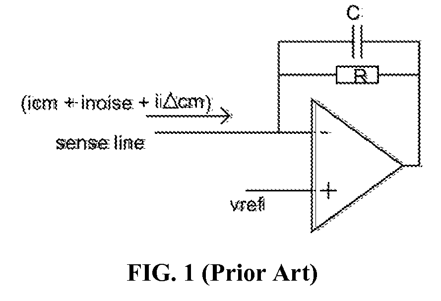
As can be seen in equation (1), the use of conventional voltage charge amplifier presents at least two problems:1. The voltage headroom of the output voltage Vout is limited by the supply voltage to the operational amplifier and the size of the integrating capacitor C. In many cases, the supply voltage attributed by the common mode and noise current occupies more than 90% of the dynamic range of the operational amplifier.
This leads to a large die size for the analog front-end circuits.

Method used


Image

  • Differential current mode analog front-end circuit for capacitive touch sensing in touchscreen panels
  • Differential current mode analog front-end circuit for capacitive touch sensing in touchscreen panels
  • Differential current mode analog front-end circuit for capacitive touch sensing in touchscreen panels

Examples


Embodiment Construction

[0027]In the following description, analog front-end circuits for enabling the capacitive touch sensing function of a capacitive touchscreen are set forth as preferred examples. It will be apparent to those skilled in the art that modifications, including additions and / or substitutions, may be made without departing from the scope and spirit of the invention. Specific details may be omitted so as not to obscure the invention; however, the disclosure is written to enable one skilled in the art to practice the teachings herein without undue experimentation.

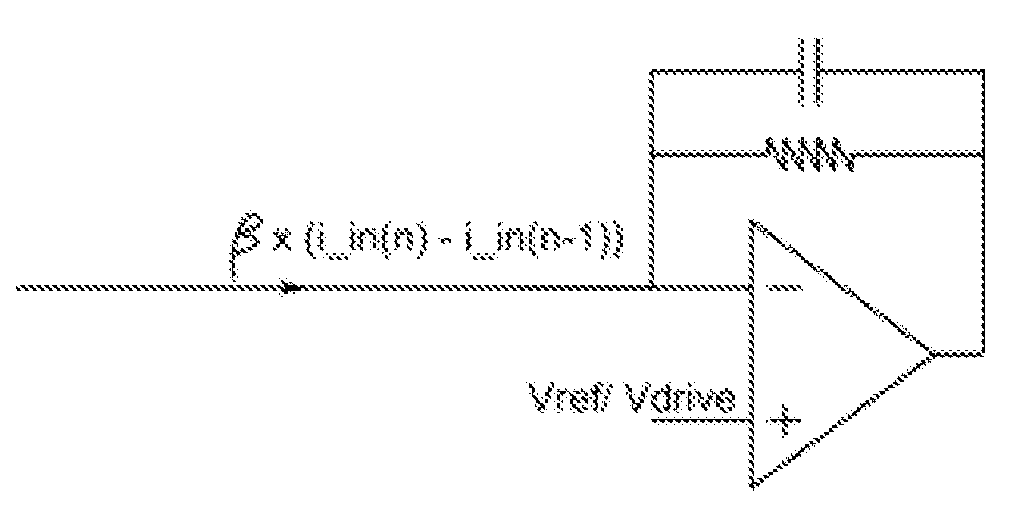
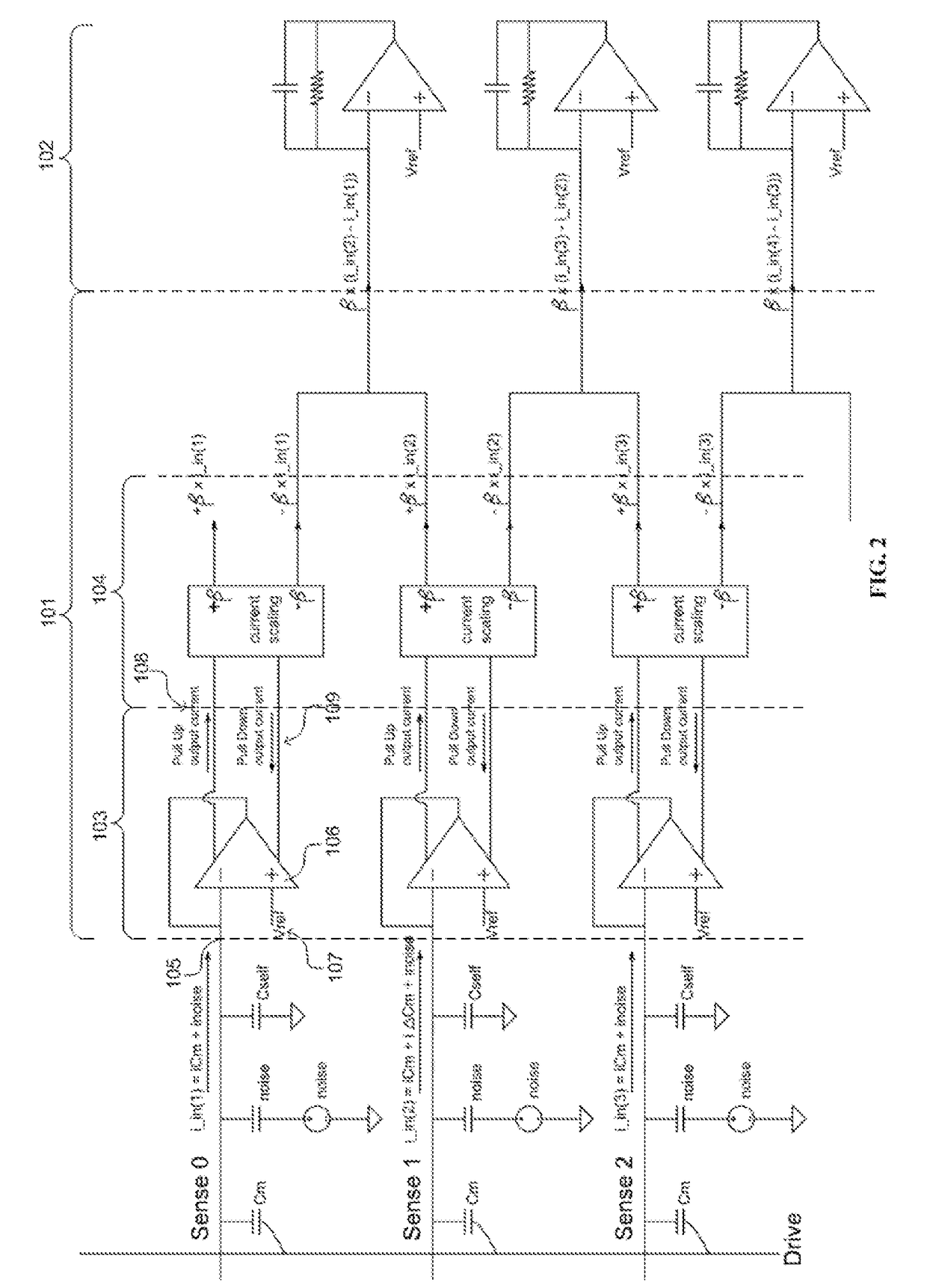
[0028]Referring to FIG. 2. In accordance to various embodiments of the present invention, the analog front-end circuit comprises a current mode differential charge amplifier 101 and a differential current to voltage converter 102. The current mode differential charge amplifier 101 can logically be divided into two stages. The first stage comprises a unity gain buffer with current replication circuit 103. The second stage comprises a...


PUM


Abstract

An analog front-end circuit comprising: a first current mode differential charge amplifier for a first sensing line, comprising: a unity gain buffer with current replication circuit, wherein the first sensing line current being fed to the unity gain buffer with current replication circuit to generate a pull up and a pull down output currents; and a current mirroring and amplification circuit, wherein the pull up and pull down output currents being fed to the current mirroring and amplification circuit to generate a positively scaled and a negatively scaled output currents; a current combining circuit for combining the positively scaled output generated for the first sensing line and a negatively scaled output current generated for a second sensing line to generate a differential current; and a differential current-to-voltage converter for converting the differential current to an output voltage usable by touch controller application.

Description

COPYRIGHT NOTICE[0001]A portion of the disclosure of this patent document contains material, which is subject to copyright protection. The copyright owner has no objection to the facsimile reproduction by anyone of the patent document or the patent disclosure, as it appears in the Patent and Trademark Office patent file or records, but otherwise reserves all copyright rights whatsoever.FIELD OF THE INVENTION[0002]The present invention generally relates to touch-sensing-enabled active matrix liquid crystal display (LCD) panels (or touchscreens). In particular, the present invention relates to the capacitive touch sensing circuitry of a capacitive touchscreen.BACKGROUND[0003]A touch-sensing-enabled active matrix LCD display panel (or touchscreen) is an active matrix LCD panel having an additional function of detecting a location of a possible finger and / or pointing device touch made on the panel. A capacitive touchscreen comprises an insulator such as glass, coated with a transparent ...

Claims


Application Information

Patent Timeline
IPC IPC(8): G06F3/041G06F3/047G06F3/044
CPCG06F3/0416G06F3/047G06F3/044G06F3/0412G06F3/04182G06F3/0418
Inventor LI, YINHO, KIN PUILAM, KUT HING
Owner SOLOMON SYSTECH
Learn More