Method and apparatus for forming porous advanced polishing pads using an additive manufacturing process

a technology of additive manufacturing and polishing pads, applied in the field of polishing pads, can solve the problems of non-uniform polishing, high cost and time-consuming methods of polishing pads manufacturing, and wear or glazed polishing pads

Active Publication Date: 2017-07-20
APPLIED MATERIALS INC
View PDF2 Cites 37 Cited by
  • Summary
  • Abstract
  • Description
  • Claims
  • Application Information

AI Technical Summary

Problems solved by technology

Eventually the polishing pad becomes worn or “glazed” after polishing a certain number of substrates, and then needs to be replaced or reconditioned.
These methods of manufacturing polishing pads are expensive and time consuming, and often yield non-uniform polishing results due to the difficulties in the production and control of the pad surface feature dimensions.
Non-uniformity has become increasingly important as the dimensions of IC dies and features continue to shrink.
Current pad materials and methods to produce them limit the manipulation and fine control bulk pad properties such as storage modulus (E′) and loss modulus (E″), which play critical roles in pad performance.
Therefore, uniform CMP requires a pad material and surface features, such as grooves and channels, with a predictable and finely controlled balance of storage modulus E′ and loss modulus E″, that are further maintained over a CMP processing temperature range, from, for example, about 30° C. to about 90° C. Unfortunately, conventional pad production via traditional bulk polymerization and casting and molding techniques only provide a modicum of pad property (e.g., modulus) control, because the pad is a random mixture of phase separated macromolecular domains that are subject to intramolecular repulsive and attractive forces and variable polymer chain entanglement.
For example, the presence of phase separated micro and macroscopic structural domains in the bulk pad may yield an additive combination of non-linear material responses, such as a hysteresis in the storage modulus E′ over multiple heating and cooling cycles that typically occur during the CMP processing of batches of substrates, which may result polishing non-uniformities and unpredictable performance across the batch of substrates.

Method used


Image

  • Method and apparatus for forming porous advanced polishing pads using an additive manufacturing process
  • Method and apparatus for forming porous advanced polishing pads using an additive manufacturing process
  • Method and apparatus for forming porous advanced polishing pads using an additive manufacturing process

Examples


process examples

Additive Manufacturing Apparatus and Process Examples

[0102]FIG. 3A is a schematic sectional view of an additive manufacturing system 350 that can be used to form an advanced polishing pad using an additive manufacturing process according to one or more embodiments of the present disclosure. An additive manufacturing process may include, but are not limited to a process, such as a polyjet deposition process, inkjet printing process, fused deposition modeling process, binder jetting process, powder bed fusion process, selective laser sintering process, stereolithography process, vat photopolymerization digital light processing, sheet lamination process, directed energy deposition process, or other similar 3D deposition process.

[0103]The additive manufacturing system 350 generally includes a precursor delivery section 353, a precursor formulation section 354 and a deposition section 355. The deposition section 355 will generally include an additive manufacturing device, or hereafter pr...

process example

Advance Polishing Pad Formation Process Example

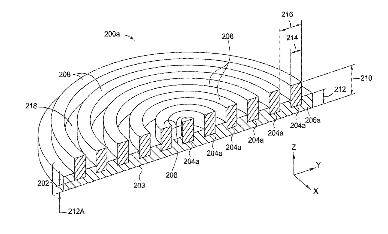
[0131]In some embodiments, the construction of an advanced polishing pad 200 begins by creating a CAD model of the polishing pad design. This can be done through the use of existing CAD design software, such as Unigraphics or other similar software. An output file, which is generated by the modeling software, is then loaded to an analysis program to ensure that the advanced polishing pad design meets the design requirements (e.g., water tight, mass density). The output file is then rendered, and the 3D model is then “sliced” into a series of 2D data bitmaps, or pixel charts. As noted above, the 2D bitmaps, or pixel charts, are used to define the locations across an X and Y plane where the layers in the advanced polishing pad will be built. In some additive manufacturing process applications these locations will define where a laser will pulse, and in other applications the location where a nozzle will eject a droplet of a material.

[0132...

reaction example 1

[0179]

As illustrated in FIG. 3D, in one embodiment, the diacrylate and diamine, may reside in two separate reservoirs 315, 316, and then may be mixed within the mixing region 318 of a tortuous path dispense nozzle 314, and dispensed as droplets, and then thermally cured with a Xenon flash lamp to form a polymer layer.

[0180]There are a number of useful acrylates that can be used to produce a Michael addition polymer, including, but not restricted to the previously described acrylates A-H. Similarly, amines that contain at least two primary or secondary amine groups may include, but are not restricted to, the previously described amines R-T. Sources for these compounds include Sigma-Aldrich of St. Louis, Mo., USA, Sartomer USA of Exton, Pa., Dymax Corporation of Torrington, Conn., USA, Allnex Corporation of Alpharetta, Ga., USA, BASF of Ludwigshafen, Germany, and Huntsman Advanced Materials, The Woodlands, Tex., USA.

[0181]In another embodiment, a printed polishing article, may be prod...


PUM


Abstract

Embodiments of the present disclosure relate to advanced polishing pads with tunable chemical, material and structural properties, and new methods of manufacturing the same. According to one or more embodiments of the disclosure, it has been discovered that a polishing pad with improved properties may be produced by an additive manufacturing process, such as a three-dimensional (3D) printing process. Embodiments of the present disclosure thus may provide an advanced polishing pad that has discrete features and geometries, formed from at least two different materials that include functional polymers, functional oligomers, reactive diluents, addition polymer precursor compounds, catalysts, and curing agents. For example, the advanced polishing pad may be formed from a plurality of polymeric layers, by the automated sequential deposition of at least one polymer precursor composition followed by at least one curing step, wherein each layer may represent at least one polymer composition, and / or regions of different compositions. Embodiments of the disclosure further provide a polishing pad with polymeric layers that may be interpenetrating polymer networks.

Description

CROSS-REFERENCE TO RELATED APPLICATIONS[0001]This application claims the benefit of U.S. Provisional Patent Application Ser. No. 62 / 304,134, filed Mar. 4, 2016, the benefit of the U.S. Provisional Patent Application Ser. No. 62 / 323,599, filed Apr. 15, 2016, the benefit of the U.S. Provisional Patent Application Ser. No. 62 / 339,807, filed May 21, 2016, the benefit of the U.S. Provisional Patent Application Ser. No. 62 / 380,334, filed Aug. 26, 2016, the benefit of the U.S. Provisional Patent Application Ser. No. 62 / 280,537, filed Jan. 19, 2016, the benefit of the U.S. Provisional Patent Application Ser. No. 62 / 331,234, filed May 3, 2016, and the benefit of the U.S. Provisional Patent Application Ser. No. 62 / 380,015 , filed Aug. 26, 2016. Each of the aforementioned patent applications are herein incorporated by reference.BACKGROUND[0002]Field[0003]Embodiments disclosed herein generally relate to polishing articles and methods for manufacturing polishing articles used in polishing proces...

Claims


Application Information

Patent Timeline
Patent Type & Authority Applications(United States)
IPC IPC(8): B24B37/24
CPCB24B37/24
Inventor GANAPATHIAPPAN, SIVAPACKIAFU, BOYICHOCKALINGAM, ASHWINREDFIELD, DANIELBAJAJ, RAJEEVORILALL, MAHENDRA C.NG, HOU T.FUNG, JASON G.YAMAMURA, MAYU
Owner APPLIED MATERIALS INC
Why Eureka
Try Eureka