Laser detection and image fusion system and method

a laser detection and image fusion technology, applied in the field of targeting systems, can solve the problems of complex task, high undesirable, and the condition is not readily detectable by the operator, and achieve the effect of eliminating background clutter and reducing the duration of exposure windows

Active Publication Date: 2017-08-03
BAE SYST INFORMATION & ELECTRONICS SYST INTERGRATION INC
View PDF0 Cites 42 Cited by
  • Summary
  • Abstract
  • Description
  • Claims
  • Application Information

AI Technical Summary

Benefits of technology

[0012]Embodiments include a laser marker and laser marker verification system comprising synchronizing an integration time of an exposure window of a first camera focal plane to an arrival of at least a single laser pulse reflected from an object, whereby the at least a single laser pulse originates from a laser source comprising and under the control of the laser marker system or originates from an external source not under control of the laser marker system; determining arrival timing of the laser pulse and focal plane array (FPA) exposure window synchronization timing for the at least a single reflected laser pulse or the series of reflected laser pulses from an adjunct system; detecting the reflected at least one laser pulse as a signal by the first camera focal plane array (FPA) with synchronous timing and minimized exposure window duration corresponding to a laser pulse event in a first image; obtaining a second image of the object without the reflected at least one laser pulse; spatially aligning the first and second images to eliminate effects of camera motion between the first and the second images; spatially correlating the location of the detected reflected at least one laser pulse in an image to corresponding locations in other acquired images; and providing an indication of the laser spot location in imagery of the object in a scene. For embodiments the at least a single pulse is a single short wave infrared (SWIR) pulse. Another embodiment comprises eliminating background clutter by subtracting the secon

Problems solved by technology

In the current state of the art, this task is complicated by several factors, not the least of which is that laser illumination sources typically utilize wavelengths invisible to the human eye in order to function covertly.
Any angular boresight error results in the laser output being directed in a direction different than where the reticle is looking.
This results the laser illuminating the incorrect location, a condition which is highly undesirable.
Further, since the laser energy is not visible, this condition is not readily detectable by the operator.
Any deviation of the object off of the detector line-of-sight will result in an imbalance in the outputs from the sensing elements, which provides an indication of the direction to the

Method used


Image

  • Laser detection and image fusion system and method
  • Laser detection and image fusion system and method
  • Laser detection and image fusion system and method

Examples


embodiment 200

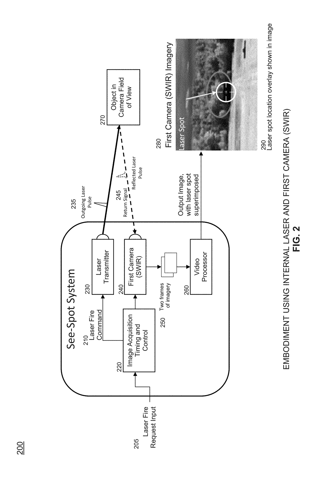
[0065]FIG. 2 depicts an embodiment 200 which incorporates internal pulsed laser transmitter 230 as the source to illuminate object 270 with laser pulse 235. Operation is as follows. The operator provides external input 205 to request that laser 230 output a pulse 235. This request is applied to Image Acquisition Timing and Control element 220 which sends Laser Fire command 210 to laser transmitter 230 to cause a laser pulse 235 to be output at the appropriate time. Image Acquisition Timing and Control element 220 provides image acquisition frame timing and exposure timing signals to First Camera 240 to control the image acquisition process. In alternative embodiments, Image Acquisition Timing and Control element 220 may instead receive some or all of these timing signals from first camera 240 as an indication of the image acquisition process occurring within that camera. The Exposure Timing and Control element determines when to initiate a laser pulse firing based on the timing of f...

embodiment 400

[0068]FIG. 4 depicts an embodiment 400 of the timing internal to the Image Acquisition Timing and Control elements (220, 320) depicted in embodiments 200 and 300 which controls the firing of a laser pulse (235, 335) by synchronizing the generation of the Laser Fire command (210, 310) such that the reflected laser pulse (245, 345) arrives at the first camera (240, 340) while the camera exposure window is open thereby acquiring energy from the scene.

[0069]The Frame Sync signal 410 is a periodic command issued by the Image Acquisition Timing and Control element to the first camera to acquire the next frame of imagery. Typically, each rising edge of the waveform initiates the acquisition of a frame of imagery. The frame time 412 is the interval between successive Frame Sync pulses.

[0070]The first camera (240, 340) begins the process of acquiring an image when it receives a Frame Sync signal 410. The camera opens the focal plane exposure window 460 which allows the pixels comprising the ...

embodiment 800

[0082]FIG. 8 depicts an embodiment 800 which is based upon use of external laser designator 890 or other external pulsed laser source as the means to illuminate object 870. Laser designator 890 is external to the invention and is not under the control of the invention.

[0083]Operation is as follows. Laser designator 890 issues outgoing laser pulses 895 in a known or otherwise predictable pattern. These pulses are reflected by object 870 being illuminated by the laser. The reflected pulses represent the return signal and are acquired by both laser receiver 830 and first camera (SWIR) 840. The output signal from laser receiver 830 is input to Pulse Repetition Frequency (PRF) Predictor element 810. The PRF Predictor analyzes the pattern of incoming laser pulses 835 allowing it to predict the arrival time of the next laser pulse. This predicted arrival time information 815 is provided to Image Acquisition Timing and Control element 820 which initiates and controls the capture of two fram...


PUM


Abstract

This invention describes a method for operating a weapon targeting system comprising the steps of using a laser to fire a single pulse at a target to obtain a reflected laser pulse; detecting the reflected laser pulse as a signal by a SWIR focal plane; detecting background illumination by using the SWIR focal plane; scene clutter filter and using optical filtering if it is necessary to suppress background illumination.

Description

RELATED APPLICATIONS[0001]This application claims the benefit of U.S. Provisional Application No. 61 / 963,352 filed Nov. 30, 2013. This application is herein incorporated by reference in its entirety for all purposes.FIELD OF THE INVENTION[0002]The invention relates to methods for targeting systems.BACKGROUND OF THE INVENTION[0003]In battlefield conditions it is often desirable to remotely identify an object as an item of interest. This is typically done using a hand-held or otherwise portable Laser Designator or Laser Rangefinder (LRF) to illuminate the object with laser energy such that an appropriate sensor system can detect the illumination and identify the object.[0004]Operators of Designator systems have an operational need to determine the specific location being illuminated by the laser radiation (the laser spot). In the current state of the art, this task is complicated by several factors, not the least of which is that laser illumination sources typically utilize wavelength...

Claims


Application Information

Patent Timeline
IPC IPC(8): G01S7/484H04N5/33G01S17/10G06T5/50G01S17/02G01S7/48G01S17/18G01S17/86G01S17/89
CPCG01S7/484G01S17/023G01S7/4808G06T2207/20224G06T5/50H04N5/332G01S17/107G06T2207/10016G06T2207/10048G06T7/74G06T7/254G01S17/89F41G3/145F41G3/06G01S17/18G01S17/86H04N23/11
Inventor CHOINIERE, MICHAEL J.CIRILLO, BRENDAN P.CONSTANTINO, ROBERT W.DEGTIAREV, EGOR V.FEDA, FRANCIS M.HU, HAIJUN H.MALLALIEU, MARK R.O'DONNELL, BRIAN F.
Owner BAE SYST INFORMATION & ELECTRONICS SYST INTERGRATION INC
Why Eureka
Try Eureka