

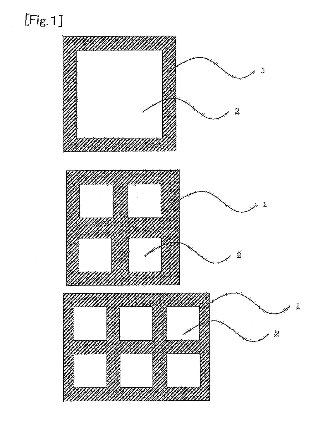
Polymer film coated with a layer of silane coupling agent
a technology of silane coupling agent and polymer film, applied in the field of polymer film, can solve the problems of brittleness, easy torn, and easy to peel a polymer film, and achieve the effect of easy peeling, relatively easy peeling, and easy peeling
- Summary
- Abstract
- Description
- Claims
- Application Information
AI Technical Summary
Benefits of technology
Problems solved by technology
Method used
Image


Examples
examples
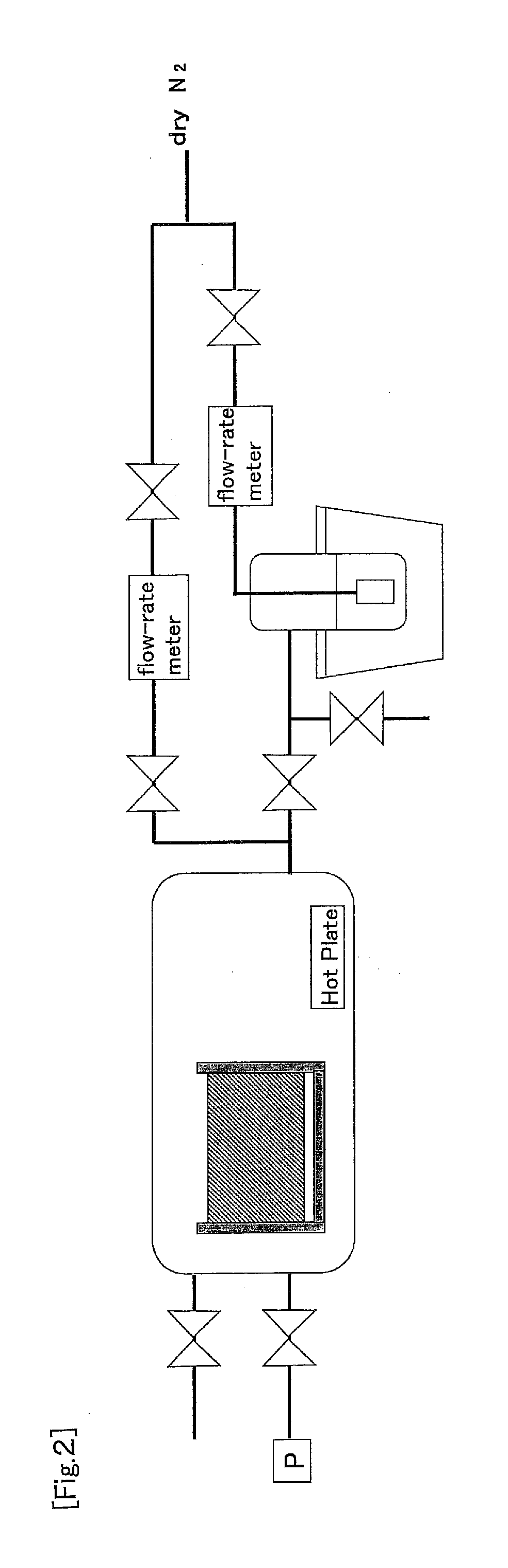
[0178]Hereinafter, the present invention will be described in more detail with reference to examples and comparative examples, but the present invention is not limited by the following examples. The methods of evaluating physical properties in the following examples are as follows.
1. Reduced Viscosity (ηsp / C) of Polyamic Acid
[0179]A solution prepared by dissolving a polymer in N-methyl-2-pyrrolidone (or N,N-dimethylacetamide) so that the polymer concentration became 0.2 g / dl was measured at 30° C. with an Ubbelohde type viscosity tube (when the solvent used for the preparation of the polyamic acid solution was N,N-dimethylacetamide, a polymer was dissolved in N,N-dimethylacetamide and the reduced viscosity was measured).
2. Thickness of Polyimide Film or the Like
[0180]The thickness was measured using a micrometer (manufactured by Feinpruf, Millitron 1245D).
3. Tensile Elastic Modulus, Tensile Breaking Strength, and Tensile Breaking Elongation of Polyimide Film
[0181]One prepared by cut...
production examples 1 and 2
(Preparation of Polyamic Acid Solutions A1 and A2)
[0220]After the inside of a reaction container equipped with a nitrogen introduction tube, a thermometer and a stirring rod was replaced with nitrogen, 223 parts by mass of 5-amino-2-(p-aminophenyl)benzoxazole and 4416 parts by mass of N,N-dimethylacetamide were added thereto and completely dissolved. Then, 217 parts by mass of pyromellitic acid dianhydride and SNOWTEX prepared by dispersing colloidal silica in dimethylacetamide (DMAC-ST30, manufactured by Nissan Chemical Industries, Ltd.) in an amount that the silica content becomes the content described in Table 1 were added thereto. The liquid was stirred at a reaction temperature of 25° C. for 24 hours, and then each of brown viscous polyamic acid solutions A1 and A2 was obtained.
TABLE 1ProductionProductionunitExample 1Example 2Polyamic acid solutionA1A2Kind of slip agentsilica—Particle size of slip agentμm0.08—Addition amount of slip agent% by mass0.350 Reduced viscosity η sp / C...
production examples 3 and 4
(Preparation of Polyamic Acid Solutions B1 and B2)
[0221]After the inside of a reaction container equipped with a nitrogen introduction tube, a thermometer and a stirring rod was replaced with nitrogen, 398 parts by mass of 3,3′,4,4′-biphenyltetracarboxylic acid dianhydride as a tetracarboxylic acid dianhydride and 147 parts by mass of paraphenylenediamine were dissolved in 4600 parts by mass of N,N-dimethylacetamide. Then, SNOWTEX prepared by dispersing colloidal silica in dimethylacetamide (DMAC-ST30, manufactured by Nissan Chemical Industries, Ltd.) in an amount that the silica content becomes the content described in Table 2 was added thereto. The liquid was stirred at a reaction temperature of 25° C. for 24 hours, and then each of brown viscous polyamic acid solutions B1 and B2 was obtained.
TABLE 2ProductionProductionunitExample 1Example 2Polyamic acid solutionB1B2Kind of slip agentsilica—Particle size of slip agentμm 0.08—Addition amount of slip agent% by mass0.40 Reduced visc...
PUM
| Property | Measurement | Unit |
|---|---|---|
| surface roughness | aaaaa | aaaaa |
| area | aaaaa | aaaaa |
| dew point | aaaaa | aaaaa |
Abstract
Description
Claims
Application Information