Synchronous powder-feeding space laser machining and three-dimensional forming method and device

a laser machining and synchronous technology, applied in the field of laser processing forming technology, can solve the problems of limited forming size, high cost, difficult coupling, etc., and achieve the effects of improving forming accuracy, simple powder beam track, and easy control

Inactive Publication Date: 2017-08-17
SUZHOU UNIV
View PDF8 Cites 36 Cited by
  • Summary
  • Abstract
  • Description
  • Claims
  • Application Information

AI Technical Summary

Benefits of technology

[0021]1. The present invention uses the hollow laser inside-laser single-beam powder-feeding method, with the track of the powder beam simple and easy to be controlled; with the gas-carried powder-feeding method, when the axis of the inside-laser powder-feeding nozzle is located in any angular position in the space, adjusting the pressure of the gas-carried powder and the pressure of the annular collimating gas in a matching way to balance the influence of gravity, so as to make the single powder beam thin, erect, collimating, and straight within a certain range, such that the laser and powder can be coupled accurately on the forming surface to allow the powder to be fed to the molten pool accurately. The present invention, under the condition that the axis of the inside-laser powder-feeding nozzle is located at any angle in the space, makes the laser beam, the gas-carried powder beam and the annular collimating gas completely coaxial, and uses the appropriate structure and size of a powder gas tube, the appropriate carried powder and annular collimating gas pressure, and the appropriate cladding process parameters; in spatial forming, both the gas-carried powder and the annular collimating gas have a forward pressure that presses the molten pool onto the forming surface, guaranteeing that the molten pool will not flow while solidifying, such that a stable molten channel can be formed on any angular base surface in the space.
[0022]2. The present invention uses a space zoning planned forming unit for the laser three-dimensional forming part, wherein each unit can be subject to different layering method and planning, the layers can be parallel or nonparallel to each other and can be equal or unequal in thickness, and the boundary layer and the filling layer of each layer can have different accumulating forming direction. Therefore, the present invention can not only complete cladding reinforcement or repair of any inclined surface in the space, but also break the limit of the traditional synchronous material-feeding laser three-dimensional forming process that a simple solid can be formed only by slicing with a horizontal plane and forming from bottom to top, allowing cladding forming and layered accumulation along different inclination direction in the space, allowing three-dimensional forming of parts containing a cantilever, a cavity and other complex structures by processing forming and continuously changing direction on any inclined base surface.
[0023]3. The present invention, for a three-dimensional solid with a slantwise overhanging surface, uses a boundary zone method for layering the boundary, i.e. always slicing perpendicularly to the overhanging slantwise boundary; in stacking accumulating forming, the laser-powder spray axis is always placed in the tangential direction of the outer surface of the forming unit, with the upper and lower layers basically all covered without dislocation, which can remove the “step effect”, improve the forming accuracy and reduce the surface roughness; in layering, the thickness of the layer can also be appropriately increased, so as to improve the forming efficiency while achieving a smoothly formed surface.

Problems solved by technology

The selective sintering method, using a powder bed as a support, can form a metal part having complex shape and an overhang, but suffers from expensive equipment, a high cost, and limited forming size.
The outside-laser powder-feeding method, converging multi-channel powder beam, has divergent powder, a coarse powder spot, only one point of convergence, and a narrow range in which the laser beam can be coupled, making coupling not easy to be done.
It can be seen from the existing synchronous powder-feeding three-dimensional forming method that, this method allows no-support free forming, and can only use the cladded molten channel in the lower layer as the support for the upper layer in the horizontal layered accumulation; when forming an overhang or a cavity structural part, the upper layer will be displaced partially relative to the lower layer to result in the “step effect” on the surface; when there is excessive or complete dislocation, light-powder leakage and molten pool flow will be caused, and even forming cannot be carried out, as shown in FIG. 3.
Under the action of a tension of the molten pool, the small dislocation between the upper and lower layers can still allow a small-angle inclined wall structure to be formed, but cannot allow a big-angle inclined part, an overhang or a cavity and other similar structural parts to be formed.
Therefore, currently the synchronous powder-feeding laser three-dimensional forming can be generally only used for the cladding reinforcement and repair in the horizontal plane and the horizontally layered three-dimensional forming, but still cannot be used for the cladding reinforcement and repair on a facade, an incline, a bottom surface or any other surface in the space and the space-layered three-dimensional forming.
This method of feeding powder from a side of the laser, not coaxially feeding the powder, is only applicable to cladding in a fixed direction, but cannot meet the requirements of facade forming for isotropy, not to mention the three-dimensional forming on any surface in the space.
Currently the synchronous powder-feeding laser three-dimensional cladding and forming method has the following shortcomings: (1) In the layered three-dimensional forming of an overhanging structural part, forming dislocation is caused at the upper and lower layers at the overhanging boundary because of no support, which will reduce the forming accuracy on the less serious occasion to result in the “step effect” on the surface, and will cause laser-powder leakage and molten pool flow on the serious occasion to make accumulating forming not sustainable; (2) it can only form an upright structure or a less outward inclined structure and other simple structures, but cannot form a greatly outward inclined structure, a cantilever or a cavity and other complex structures; and (3) it can only allow cladding process, repair or forming of a horizontal plane or a small-angle incline, but cannot allow cladding process, repair or three-dimensional accumulating forming on any inclines in the space.

Method used


Image

  • Synchronous powder-feeding space laser machining and three-dimensional forming method and device
  • Synchronous powder-feeding space laser machining and three-dimensional forming method and device
  • Synchronous powder-feeding space laser machining and three-dimensional forming method and device

Examples


example 1

[0038]A method for synchronous powder-feeding space laser cladding and three-dimensional forming is provided, comprising the following steps:

[0039](1) Dividing a multi-branch complex three-dimensional solid expected to be formed into one or more forming units based on the body simplification and nozzle cladding scanning accessibility principle, and selecting the forming sequence of each unit in turn, with each forming unit having a respective optimal forming growth direction and rule;

[0040](2) dividing the forming unit obtained in the step (1) into a number of layers along the stacking accumulating direction, each layer at least including one of the filling region and the boundary region;

[0041](3) using a hollow annular laser inside-laser single-beam gas-carried powder-feeding method to control a mechanical arm to drive an inside-laser powder-feeding nozzle to scan and move in the boundary region and the filling region of a layer along a predetermined track, so as to complete claddi...

example 2

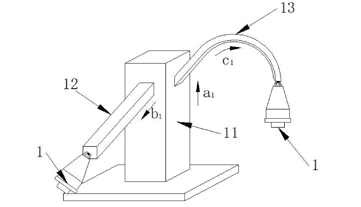
[0047]As shown in FIG. 6, dividing the three-branch three-dimensional forming into three simple-shaped forming units a, b and c according to the body simplification and inside-laser powder-feeding nozzle accessibility principle; wherein the forming unit a11 has a forming growth direction a1, the forming unit b12 has a forming growth direction b1, and the forming unit c13 has a forming growth direction c1. The forming sequence is as follows: First forming the forming unit a11, then controlling the mechanical arm 7 to move the inside-laser powder-feeding nozzle 1 to the start position of the forming unit b12 to form the forming unit b12 on the sidewall of the forming unit a11, and then controlling the mechanical arm 7 to move the inside-laser powder-feeding nozzle to the start position of the forming unit c13 to form the forming unit c13 on the other side of the forming unit a11, and so on, until completing the unit accumulation of the entire three-branch three-dimensional solid.

example 3

[0048]The synchronous powder-feeding space laser cladding and three-dimensional forming of the curved overhanging structural part is shown in FIGS. 7 and 8, which uses a zoning method, dividing the forming unit along the optimal growth accumulation direction into a number of layers, with each layer divided into a boundary region 18 and a filling region 16. The layering principle of the boundary region 18 is as follows: Always slicing along a direction perpendicular to the boundary face 17, i.e. along the normal direction of the boundary face; when the boundary face is straight faced, the layers are parallel to each other; when the boundary face is a curved surface, the layers can be neither parallel to each other nor equal in thickness. The layering principle of the filling region 16 is as follows: All the layers are parallel to the base surface 19 and also parallel to each other. After cladding forming a layer, the nozzle retreats by a distance of thickness of one layer along the g...


PUM

PropertyMeasurementUnit
lengthaaaaaaaaaa
lengthaaaaaaaaaa
thicknessaaaaaaaaaa

Abstract

A method for synchronous powder-feeding space laser cladding and three-dimensional forming includes: dividing a three-dimensional solid into a plurality of forming units according to a form simplification and nozzle cladding scanning accessibility principle, and dividing each forming unit into a plurality of layers; employing a single-beam gas-carried power-feeding mode in a hollow annular laser; controlling a mechanical arm (7) to drive an in-laser powder-feeding nozzle (1) to move and scan along a predetermined trajectory in a filling area and a boundary area of the layer; and sequentially conducting cladding and stacking formation of the layer for the entire unit. A device includes an inside-laser powder-feeding nozzle (1), a laser generator (6), a mechanical arm (7), a control module (4), a transmission optical fiber (5), a gas-carried powder feeder (3) and a gas source (2).

Description

TECHNICAL FIELD[0001]The present invention relates to a laser processing forming technology, particularly to a method and device for synchronous powder-feeding space laser cladding and three-dimensional forming.BACKGROUND TECHNOLOGY[0002]The additive manufacturing technology is a technology that manufactures a solid part by gradually adding materials. There are two common laser additive manufacturing methods for metal, laser powder-bed selective sintering melting and laser synchronous material-feeding cladding forming. The selective sintering method, using a powder bed as a support, can form a metal part having complex shape and an overhang, but suffers from expensive equipment, a high cost, and limited forming size. Cladding forming metal by the laser synchronous material-feeding method can approach or achieve performance of forgings at a low cost, and can be integrated with various CNC machine tools, mobile robots and so on to freely form a large three-dimensional solid; it can cl...

Claims


Application Information

Patent Timeline
Patent Type & Authority Applications(United States)
IPC IPC(8): B22F3/105B23K26/144B33Y30/00B23K26/08B33Y10/00B23K26/342B23K26/14
CPCB22F3/1055B23K26/342B23K26/144B23K26/1476B22F2998/10B33Y10/00B33Y30/00B22F2003/1057B23K26/0884B22F5/10B22F7/062Y02P10/25B22F10/30B22F12/53B22F10/385B22F10/25B22F10/322B22F3/105
Inventor SHI, SHIHONGSHI, TUOFU, GEYANZHU, GANGXIANSHI, JIANJUNLEI, DINGZHONGMENG, WEIDONG
Owner SUZHOU UNIV
Why Eureka
Try Eureka