Light source

a light source and white light technology, applied in the field of efficient white light emitting diodes, can solve the problems of high maintenance cost, high electrical energy consumption of light sources, and high energy consumption of phosphor, and achieve the effects of reducing the operational temperature of phosphor, reducing excessive heat, and reducing the operating temperature of phosphor

Active Publication Date: 2017-08-24
CRYTUR SPOL SRO
View PDF13 Cites 9 Cited by
  • Summary
  • Abstract
  • Description
  • Claims
  • Application Information

AI Technical Summary

Benefits of technology

[0047]In another preferable embodiment of the light source according to the invention, the single crystal phosphor is connected with a cooler. The cooler removes excessive heat, maintains a lower operational temperature of the phosphor and thus positively influences the durability of the light source.
[0048]In another preferable embodiment of the light source according to the invention, the source of the excitation coherent radiation and the single crystal phosphor are connected with a light guiding optic fibre or are connected with a light conducting planar optic waveguide, where the optic waveguide is connected to the single crystal phosphor with an optical bonding. To reduce the transfer of heat from the phosphor to the excitation source laser diode, it is good to separate both the members from each other, and to ensure the impinging of the excitation light on the phosphor excitation surface, it is possible to conduct the light beam via an optic fibre or an optic waveguide.
[0049]In another preferable embodiment of the light source according to the invention, there is an optic lens between the excitation coherent radiation source and the single crystal phosphor to scatter the excitation coherent radiation on the excitation surface of the single crystal phosphor. The optic lens distributes the excitation radiation spot beam onto the whole excitation phosphor surface which heats up evenly, as opposed to spot lighting, and thus extends its durability.

Problems solved by technology

The disadvantages of this procedure consist of the fact that lighting requires a higher electrical energy consumption, that is by three laser diodes at the same time, and, furthermore, the light sources requires very exact optics for mixing the laser beams in one white light beam.
When doing so, there are energy losses in the phosphor both due to the conversion itself (Stokes shift) and to the light scattering or reflection.
The rotating parts are, however, generally more demanding for construction, maintenance and, particularly, operation and are a potential source of defects.
This solution is not suitable for the general application and therefore a static solution must be found.
When illuminating phosphors, assembled in various matrixes, with a laser light beam of the 1 W output, the matrixes based on polycarbonates, glass or aluminium are damaged after 5 minutes due to the released heat.
Under high temperatures, there occur negative phenomena too, such as temperature luminescence quenching, and the whole light source can be overheated which furthermore increases the demands on cooling.
One of the disadvantages of utilizing laser diodes is due to the fact that with laser diodes there is a large thermal dependence since the increase in the temperature on the laser diode causes a significant decrease in its efficiency and shortening of its life.
This results in higher heat generation in the phosphor which, if it is not efficiently taken away, may heat up the phosphor to temperatures exceeding 200° C. and there may occur temperature quenching of the luminescence which denotes thermally dependent non-radiant processes that decrease luminescent efficiency.
The disadvantages of the above described solution consist of the fact that their absorption and emission spectra cannot be shifted in such a manner that the resulting light meets the conditions for non-disturbing long-term lighting of e.g. households.
The excitation source from the light emitting diodes does not attain the above stated quality of the laser diode light beam, therefore the light sources produced in this way are not very powerful.
The disadvantages of this solution again consist in LEDs being used as an excitation light source.
The disadvantages of the stated solution consist in the fact that due to the chemical composition of the single crystal phosphor it is not possible to shift the limits of the absorption and emission spectra of this single crystal phosphor.
The disadvantages of the stated single crystal material consist in its not being suitable for light sources for general usage, e.g. in households.
The used excitation radiation is harmful to the health and is not suitable for common light application.
Polycrystalline phosphors, useable for light sources according to the current state of technology, have the following disadvantages which consist in the utilization of unsuitable excitation radiation, in their polycrystalline structure which leads to energy losses, in complicated realization of rotational phosphors and in worse heat management, leading to quenching and damage of radiation sources.
Furthermore, the excitation radiation source is either harmful to the health, that is gamma, X-ray and UV excitation radiation, or the excitation radiation source is not sufficiently efficient as in case of e.g. LED excitation radiation sources whose light beam luminance is low and the light beam is divergent.
The known single crystal phosphors combined with excitation radiation laser sources are of such a construction that they do not enable the shift of the emission and absorption spectra, therefore the extracted light must be further combined and, as a result, such light sources are bigger and more costly.

Method used


Image

  • Light source
  • Light source
  • Light source

Examples


Embodiment Construction

[0069]It is understood that the below stated and depicted specific embodiments of the invention are represented for illustration and not as the limitation of the embodiments of the invention to the stated embodiments. Experts familiar with the state of the art will find or will be able to ensure, when performing routine experimentation, larger or smaller amount of equivalents to the specific embodiments of the invention which are described here. These equivalents shall be included in the extent of the following claims too.

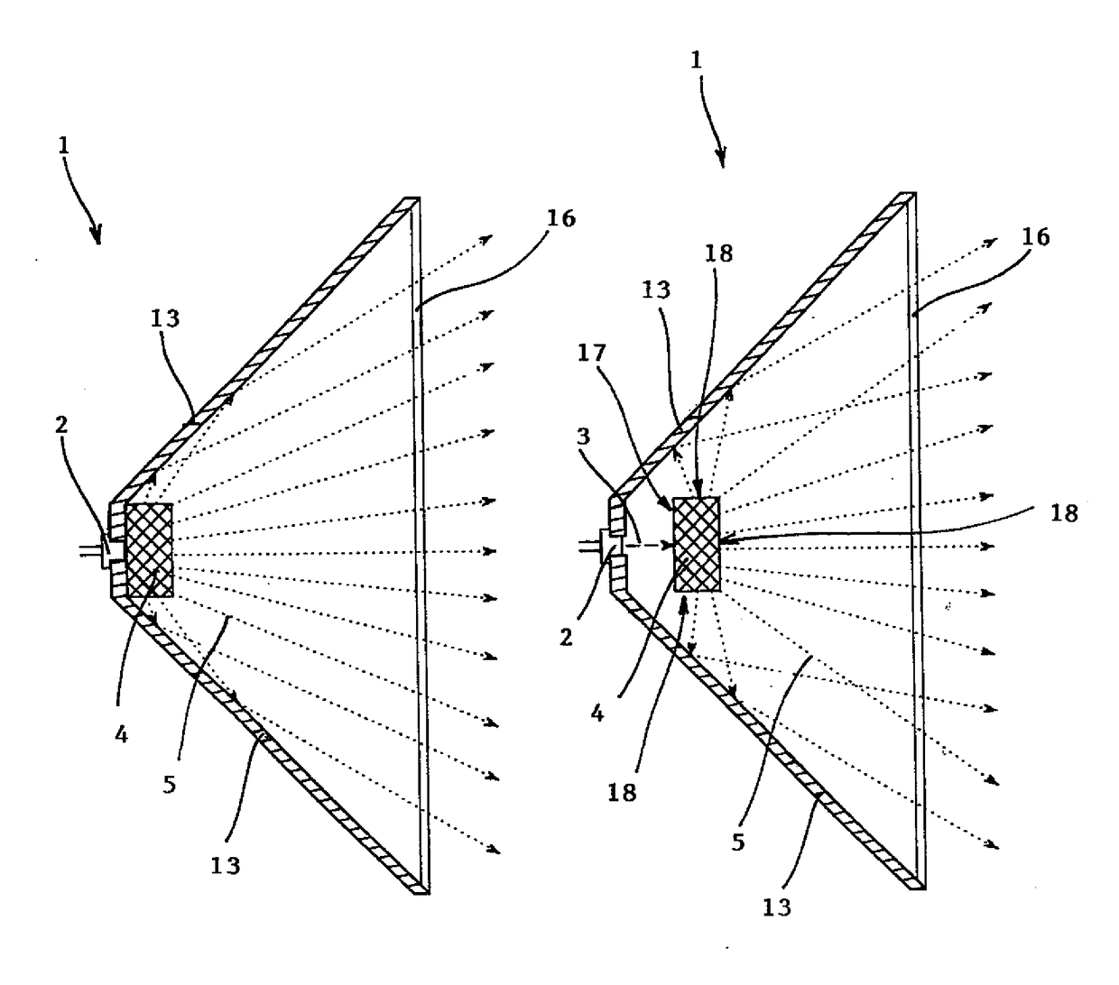
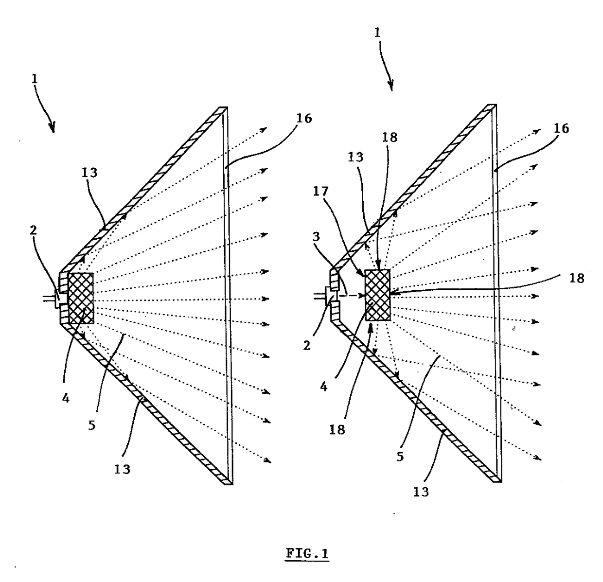
[0070]The light source 1 is depicted in a simplified manner in FIG, 1 where we can see it in cross-section. The basic parts of the light source 1 are the solid-state laser source 2 of the excitation coherent radiation 3 to which a single crystal phosphor 4 is fixed, or, possibly, the single crystal phosphor 4 is located in a more remote position from the source of the excitation coherent radiation 3. The single crystal phosphor 4 emits extracted light 5 which is di...


PUM

PropertyMeasurementUnit
temperatureaaaaaaaaaa
light wavelengthsaaaaaaaaaa
wavelengthsaaaaaaaaaa

Abstract

The light source is based on a high-efficiency solid-state laser source of the excitation coherent radiation and a single crystal phosphor which is machined in a form of an optic element for emitted light parameterisation. The single crystal phosphor is produced from a single crystal material on the basis of garnets of the (Ax, Lu1-x)aAlbO12:Cec general formula or from a single crystal material on the basis of perovskite structure of the B1-qAlO3:Dq general formula. The efficient light source shall be utilized e.g. in the automotive industry.

Description

FIELD OF THE INVENTION[0001]The invention relates to efficient white light emitting diodes for generally widespread utilization, including luminescent material emitting light in dependence on the luminescent material excitation with excitation coherent radiation.BACKGROUND OF THE INVENTION[0002]Currently, the lighting technology utilizes a wide spectrum of light sources, such as light sources with filaments, halogen light sources, high-intensity discharge lamps (HID), fluorescent lamps and, lately, more and more often semi-conductor light sources, such as light emitting diodes (LED). The alternative to the currently introduced light sources of the LED type appears to be a laser diode (LD). The laser diode is, same as the LED, a semi-conductor device which converts electrical energy directly into light.[0003]Currently, the output of the blue laser diodes as one of the types of solid-state source of coherent light progressed significantly and it is therefore possible to consider the u...

Claims


Application Information

Patent Timeline
Patent Type & Authority Applications(United States)
IPC IPC(8): F21V9/16F21V9/08F21V15/01C09K11/77F21V3/00
CPCF21V9/16C09K11/7774C09K11/7706F21Y2115/30F21V15/01F21V9/08F21V3/00C09K11/7792F21V13/12F21Y2101/00F21K9/61F21K9/64G02B6/0008F21Y2115/10H01S5/02212H01S5/4025F21V9/30F21V13/14F21V9/32F21V9/38H01S5/0087H01S5/02251H01S5/0225C09K11/57C09K11/68Y02B20/00C09K11/7721F21S15/00
Inventor FIDLER, TOMASKUBAT, JANNOVOTNY, STEPANHOUZVICKA, JINDRICH
Owner CRYTUR SPOL SRO
Why Eureka
Try Eureka