

R-t-b based permanent magnet
- Summary
- Abstract
- Description
- Claims
- Application Information
AI Technical Summary
Benefits of technology
Problems solved by technology
Method used
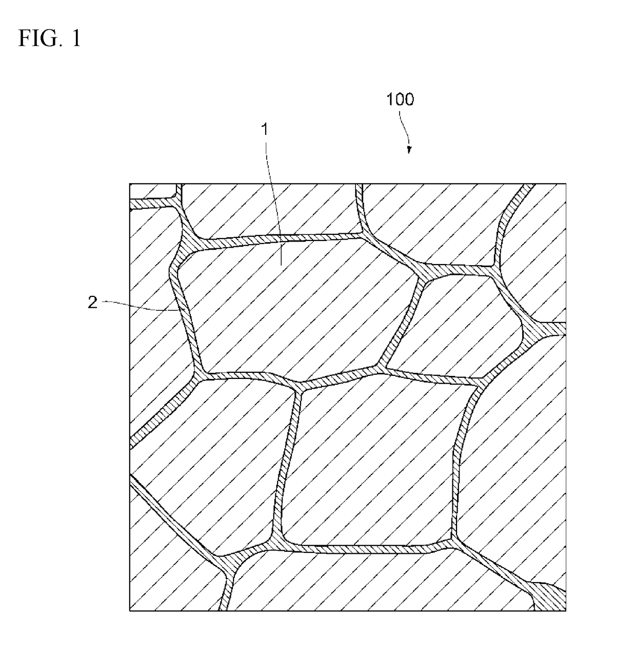
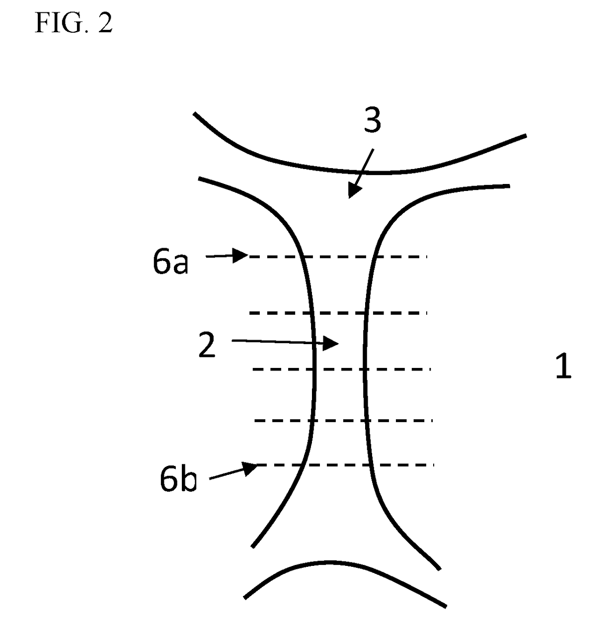
Image

Examples
experimental examples 1 to 6
[0080]First, raw material metals of an R-T-B based permanent magnet were prepared, and a raw material alloy was prepared by a strip casting method so that the R-T-B based permanent magnet having composition “A” shown in Table 1 was obtained. Incidentally, in Table 1, “bal.” is a balance provided that a total composition of each alloy is 100 mass %, and “T.RE” is a total mass % of rare earth elements.
TABLE 1Composition (mass %)CorrespondingBNdPrDyT. REGaAlCoCuZrFeExamplesComposition0.8923.006.002.0031.000.300.201.001.000.40bal.1 to 6“A”Composition0.8032.000.000.0032.000.500.201.500.601.00bal. 7 to 10“B”Composition0.8432.700.000.0032.700.900.200.500.402.00bal.11 to 20“C”
[0081]Next, a hydrogen pulverization treatment for storing hydrogen in the obtained raw material alloy and then performing dehydrogenation in an Ar atmosphere at 500° C. for 1 hour was carried out. Thereafter, the obtained coarse powder was cooled to a room temperature in the Ar atmosphere.
[0082]An oleic amide of 0.15 ...
experimental examples 7 to 10
[0092]Raw materials were blended so that an R-T-B based permanent magnet of composition “B” shown in Table 1 was obtained, and casting of a raw material alloy and a hydrogen pulverization treatment were carried out in the same manner as Experimental Example 1.
[0093]An oleic amide of 0.4 mass % as a pulverization aid was added to the obtained coarse powder of composition “B”, and this was mixed. Then, a fine pulverization was performed using a jet mill. A classification condition was adjusted in the same manner as Experimental Example 1, and a fine powder was prepared so that the main-phase crystal grains of the R-T-B based permanent magnet had an average grain size of 1.5 to 1.6 μm.
[0094]Pressing, sintering, and aging treatment were performed to the obtained fine powder in the same manner as Experimental Example 1, and respective R-T-B based permanent magnets of Experimental Examples 7 to 10 were obtained. Table 3 shows treatment conditions of Aging 2.
[0095]As is the case with Exper...
experimental examples 11 to 20
[0098]Raw materials were blended so that an R-T-B based permanent magnet of composition “C” shown in Table 1 was obtained, and casting of a raw material alloy and a hydrogen pulverization treatment were carried out in the same manner as Experimental Example 1.
[0099]In Experimental Examples 11 to 20, Experimental Examples 11 to 15, where a dry pulverization was carried out using a jet mill, and Experimental Examples 16 to 20, where a wet pulverization was further carried out using a bead mill after the dry pulverization was carried out, were compared in terms of a fine pulverization method.
[0100]An oleic amide of 0.8 mass % as a pulverization aid was added to the obtained coarse powder of composition “C”, and this was mixed. Then, a fine pulverization was performed as a dry pulverization using a jet mill. In the fine pulverization, a classification condition of the jet mill was changed to adjust a pulverization particle size of the fine powder and adjust the average grain size of the...
PUM
| Property | Measurement | Unit |
|---|---|---|
| Fraction | aaaaa | aaaaa |
| Percent by mass | aaaaa | aaaaa |
| Percent by mass | aaaaa | aaaaa |
Abstract
Description
Claims
Application Information