Motor control device and motor control method

a technology of motor control and control device, which is applied in the direction of electric generator control, dynamo-electric converter control, dynamo-electric gear control, etc., can solve the problems of microcomputer processing load increase, low-frequency fold-back noise, and may occur, and achieve simple configuration, reduce processing load, and ensure torque accuracy

Active Publication Date: 2017-10-05
MITSUBISHI ELECTRIC CORP
View PDF2 Cites 7 Cited by
  • Summary
  • Abstract
  • Description
  • Claims
  • Application Information

AI Technical Summary

Benefits of technology

[0022]According to the present invention, it is possible to provide a simple configuration wherein the harmonic components synchronized with the rotor position are extracted by the first computation cycle, and furthermore, a fundamental wave component can be extracted on the basis of a second computation cycle which is shorter than the first computation cycle, and a feedback current value can be generated from both components. As a result of this, is it possible to obtain a motor control device and motor control method capable of ensuring torque accuracy by suppressing the occurrence of low-frequency fold-back noise caused by aliasing, while also restricting increase in the computational processing load, as well as being able to ensure control stability with respect to environmental variations, such as angular error, power voltage ripples, and the like.

Problems solved by technology

However, the prior art involves the following problems.
In the discrete-system computation process performed by the microcomputer, if the sampling cycle is longer than ½, then low-frequency fold-back noise, which is not present in the actual signal, may occur.
Meanwhile, if the control frequency is shortened in order to raise the accuracy of current detection, the processing load on the microcomputer increases.

Method used


Image

  • Motor control device and motor control method
  • Motor control device and motor control method
  • Motor control device and motor control method

Examples


first embodiment

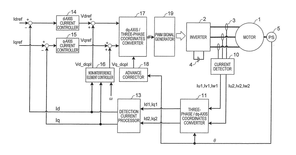
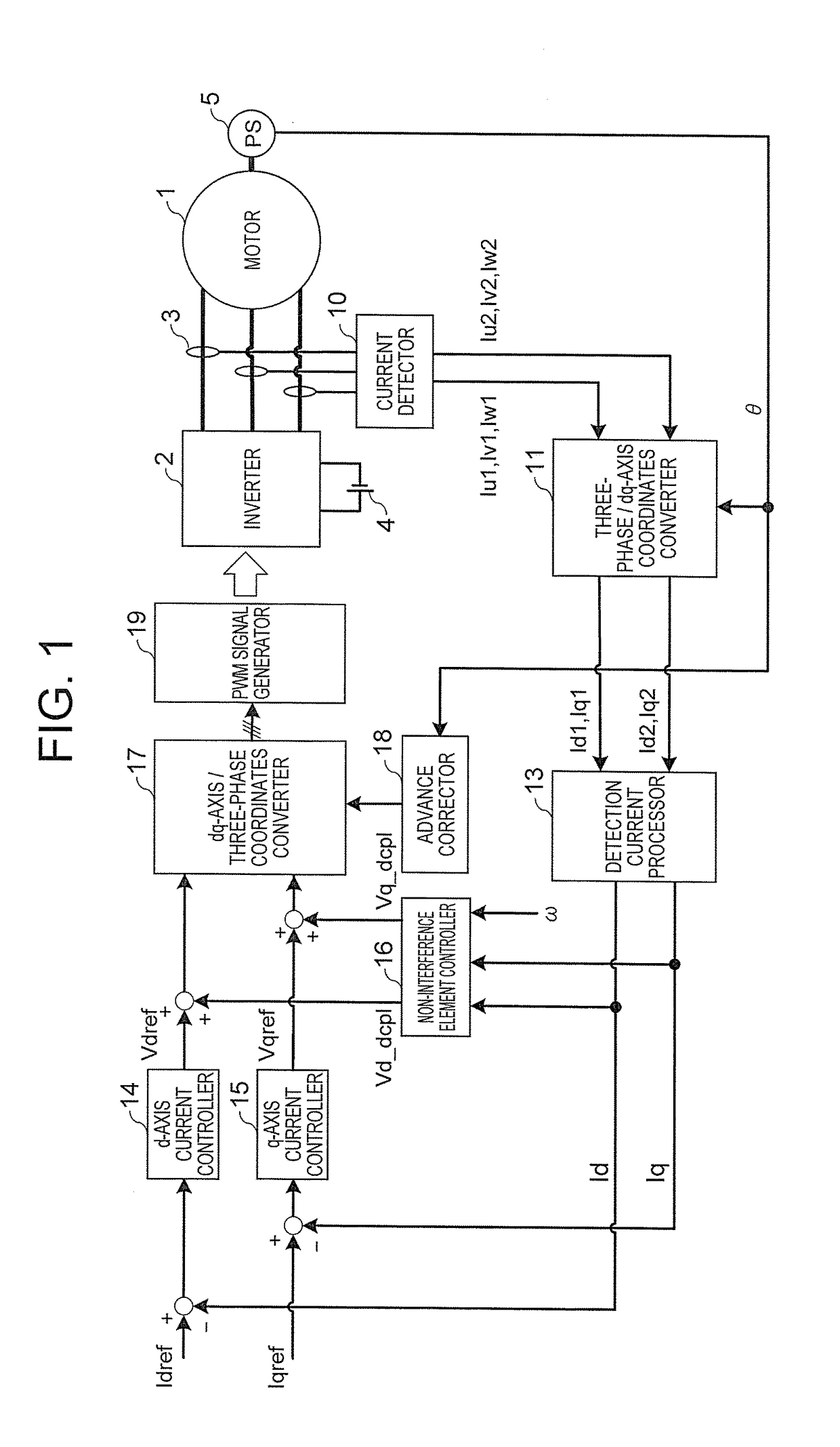
[0033]FIG. 1 is a block diagram showing a configuration of the motor control device according to a first embodiment of the present invention. The motor control device and motor control method according to the first embodiment can be applied to a drive system using a motor of any other type, as well as the motor of an electric automobile or a hybrid automobile.

[0034]In FIG. 1, a motor 1 receives a supply of electricity and is driven by using an inverter 2 which converts between direct and alternating current. A current sensor 3 which detects a three-phase current is provided on the AC side of the inverter 2. A DC power source 4 is connected to the DC side of the inverter 2. Furthermore, the rotor position detector 5 is connected to the motor 1.

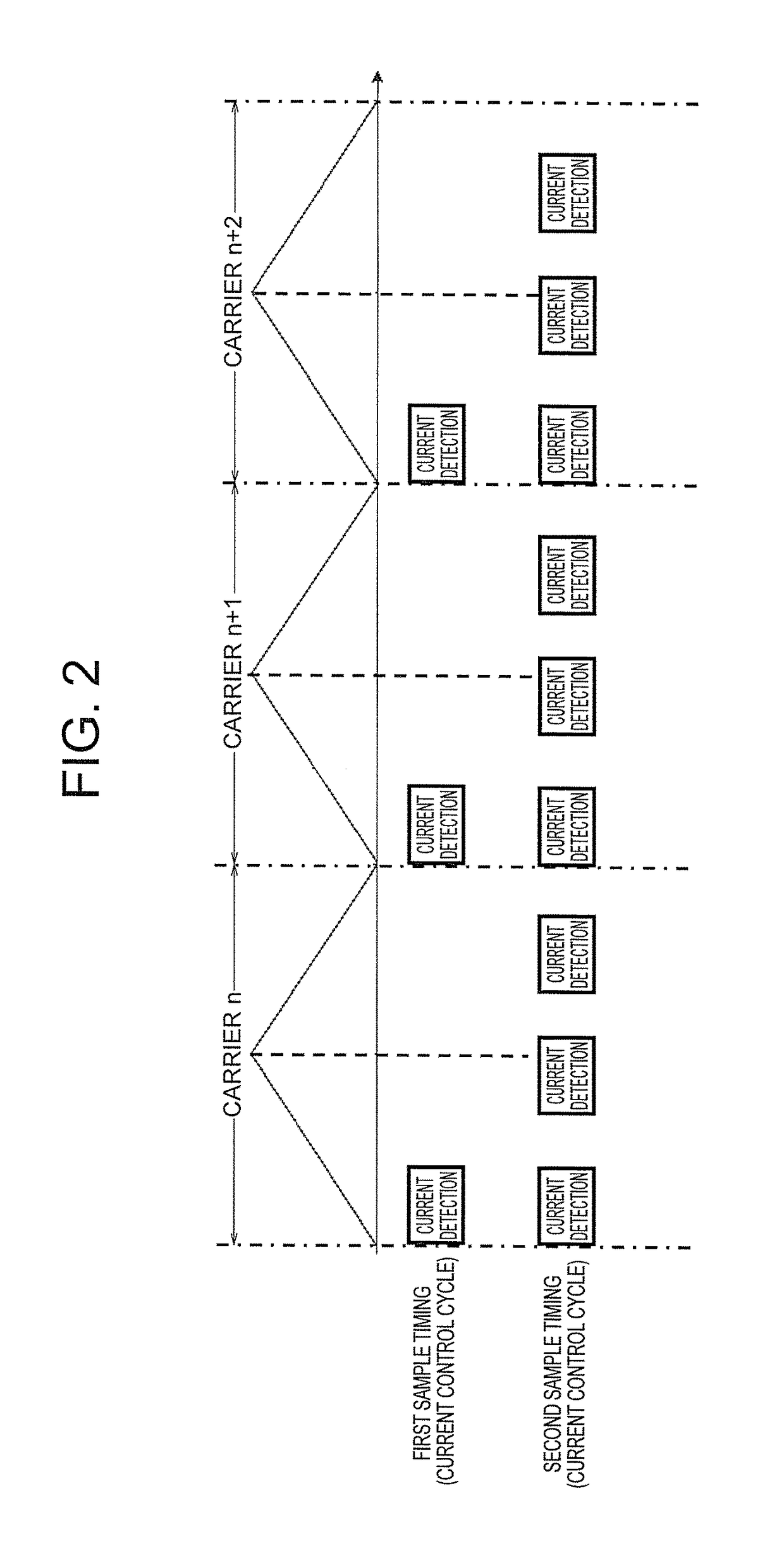
[0035]A current detector 10 detects the output signal of the current sensor 3 at different detection cycles (a first sample timing and a second sample timing). A three-phase / dq-axis coordinates converter 11 reads in the output signal of the rot...

second embodiment

[0079]FIG. 6 is a block diagram illustrating the internal configuration of the detection current processor 13 in a motor control device according to a second embodiment of the present invention. The detection current processor 13 extracts the AC components from Id1, Iq1 computed at the first computation cycle, via the high-pass filter 13a, and then multiplies by a predetermined coefficient K in a multiplier 13b.

[0080]Here, the coefficient K can change in accordance with the rotational speed, torque value and voltage. By varying the coefficient K, it is possible to suitably compensate the low-order harmonic components which differ according to the operational state of the motor.

[0081]On the other hand, the currents Id2, Iq2 computed at the second computation cycle are fundamental wave components from which harmonic components have been removed via the low-pass filter 12 shown in FIG. 5 above. Therefore, the detection current processor 13 according to the second embodiment calculates...

third embodiment

[0084]FIG. 7 is a block diagram showing a range for processing at a first computation cycle and a range for processing at a second computation cycle, from the three-phase current detection to the voltage command output, in a motor control device according to a third embodiment of the present invention.

[0085]Compared to the configuration in FIG. 5 according to the first embodiment, the configuration in FIG. 7 according to the third embodiment differs in that the second computation cycle is a random cycle, and furthermore the low-pass filter 12 is not provided.

[0086]Furthermore, FIG. 8 is a block diagram having a different configuration to FIG. 7, showing the range for processing at the first computation cycle and the range for processing at the second computation cycle, from the three-phase current detection to the voltage command output, in the motor control device according to the third embodiment of the present invention.

[0087]Compared to the configuration in FIG. 5 according to t...


PUM


Abstract

An object is to ensure torque accuracy by suppressing the occurrence of low-frequency fold-back noise caused by aliasing, and stable control performance with respect to environmental variations, such as angular errors, power voltage ripples, and so on.
A motor control device includes a current detector (10) which, in generating a feedback current value on the basis of the detection result of a three-phase AC current supplied from an inverter (2) to a motor (1), generates a first current detection value based on a first sample timing and a second current detection value based on a second sample timing that is shorter than the first sample timing; a coordinates converter (11) which converts the coordinates of the first current detection value and the second current detection value to q and d axes; and a detection current processor (13) which generates a feedback current value from the coordinate conversion results.

Description

BACKGROUND OF THE INVENTION1. Field of the Invention[0001]The present invention relates to a motor control device and a motor control method wherein an AC motor such as a permanent magnet synchronous motor, induction motor or reluctance motor is controlled by an inverter.2. Description of the Related Art[0002]A prior art method for controlling an AC motor is known in which a voltage applied from an inverter to a motor is controlled by performing control operations to convert the detection result of a value of current flowing in the AC motor, to two axis components on a rotational coordinates system (see, for example, Japanese Patent Application Publication No. 2011-83068).[0003]More specifically, this prior art performs control by the following procedure.[0004]The current value detected by a current sensor provided on the three-phase AC side of the inverter is converted into two axis components on a rotational coordinates system which is synchronized with the position of the rotor o...

Claims


Application Information

Patent Timeline
Patent Type & Authority Applications(United States)
IPC IPC(8): H02P21/22H02P6/14H02P27/08
CPCH02P21/22H02P6/14H02P27/08H02P21/05H02P21/14H02P29/50
Inventor TACHIBANA, TOMOYAIEZAWA, MASAHIROMATSUURA, DAIKIWADA, NORIYUKI
Owner MITSUBISHI ELECTRIC CORP
Why Eureka
Try Eureka