Processes for selective recovery of rare earth metals present in acidic aqueous phases resulting from the treatment of spent or scrapped permanent magnets

a technology extraction methods, applied in the direction of process efficiency improvement, rare earth metal nitrates, chemistry apparatus and processes, etc., can solve the problems of not being able to adapt the use of extractants to the recovery generating supply risks of rare earth metals for the market, and not being very interesting industrially

Active Publication Date: 2017-10-12
COMMISSARIAT A LENERGIE ATOMIQUE ET AUX ENERGIES ALTERNATIVES
View PDF0 Cites 3 Cited by
  • Summary
  • Abstract
  • Description
  • Claims
  • Application Information

AI Technical Summary

Problems solved by technology

This specificity, combined with a growth in the worldwide demand for rare earth metals as well as with a limited number of countries producing rare earth metals, generate supply risks of these metals for the markets.
However, the use of these extractants is not adapted to the recovery of the rare earth metals present in an acid aqueous phase stemming from the processing of permanent magnets NdFeB since they all have the drawback of strongly extracting the iron as well as the other transition metals.
Their use would therefore require removal of the transition metals from the aqueous phase before extracting therefrom the rare earth metals, which would lead to a wieldy method to be applied and therefore not very interesting industrially.
Finally, no scheme of a method which would allow recovery, at an industrial scale, of dysprosium and, optionally, of praseodymium and of neodynium both quantitatively and selectively is proposed in this article which is exclusively based on experiments in test tubes.

Method used


Image

  • Processes for selective recovery of rare earth metals present in acidic aqueous phases resulting from the treatment of spent or scrapped permanent magnets
  • Processes for selective recovery of rare earth metals present in acidic aqueous phases resulting from the treatment of spent or scrapped permanent magnets
  • Processes for selective recovery of rare earth metals present in acidic aqueous phases resulting from the treatment of spent or scrapped permanent magnets

Examples


example 1

Scheme of a Preferred Embodiment of the First Method of the Invention

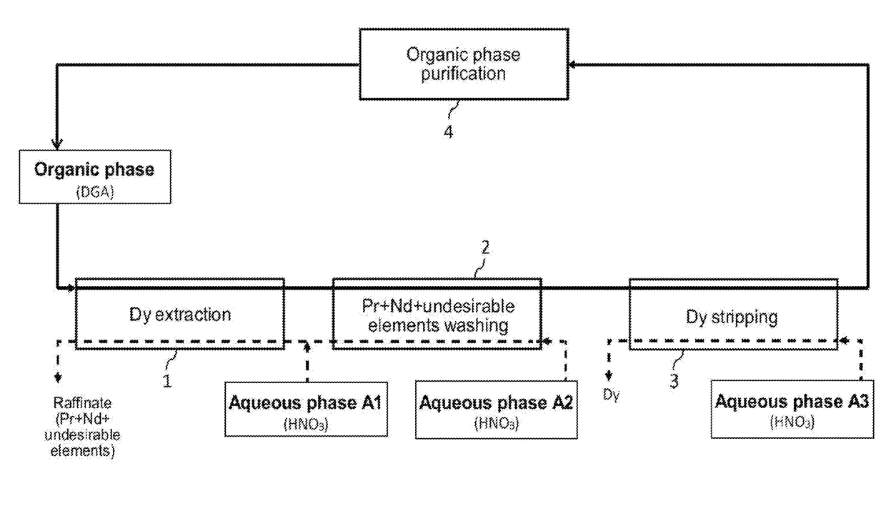
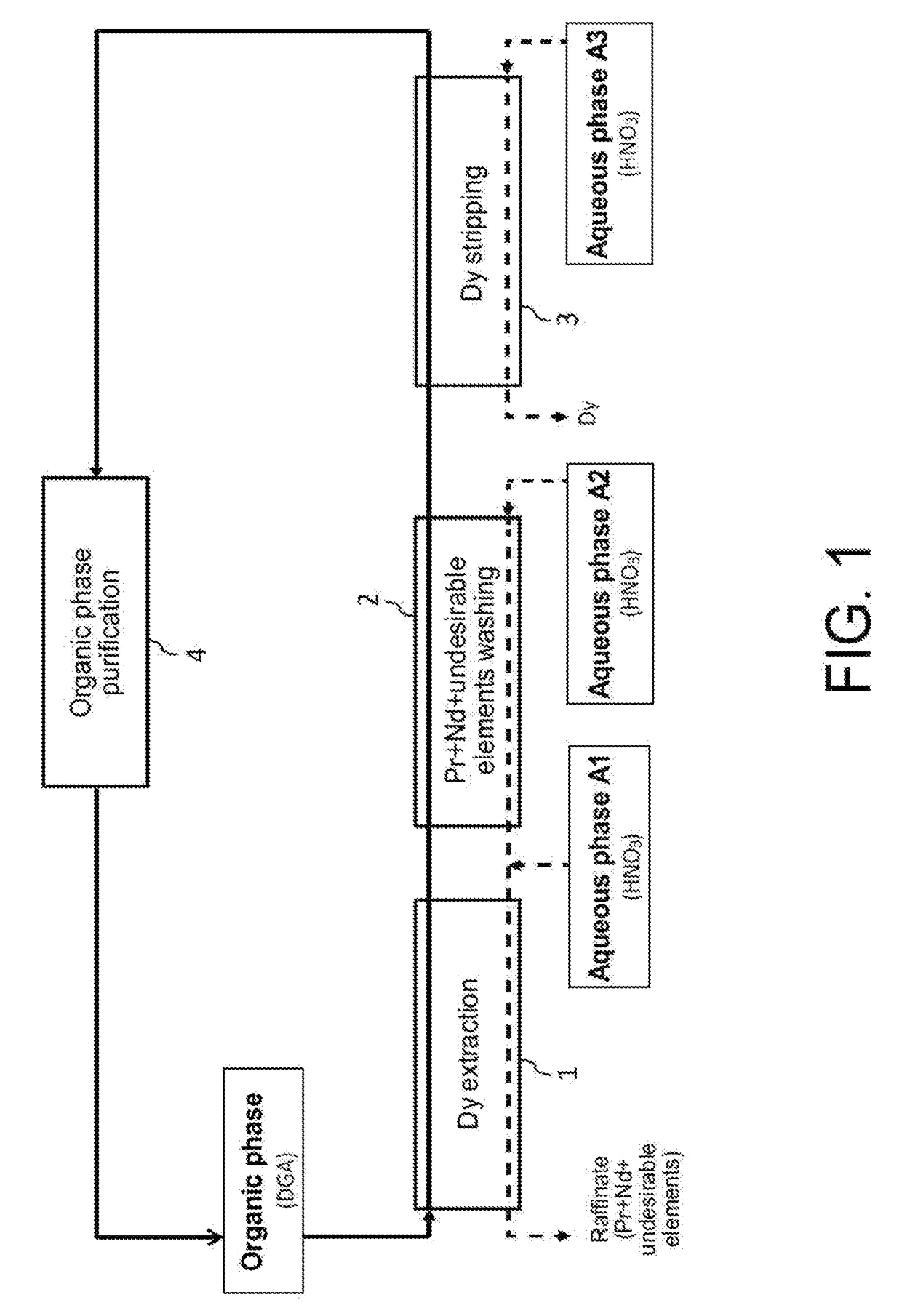
[0094]Reference is made to FIG. 1 which illustrates the principle of a preferred embodiment of the first method of the invention, designed for processing, at an industrial scale, a nitric aqueous phase stemming from the processing of spent or scrapped permanent magnets NdFeB, with view to selectively recovering dysprosium which is the most interesting economically one of the heavy rare earth metals present in this aqueous phase.

[0095]This aqueous phase is for example an aqueous phase stemming from the dissolution in a nitric medium, supplemented with an oxidizer, of a powder of permanent magnets NdFeB as obtained in the aforementioned reference [2].

[0096]Such an aqueous phase, which is designated hereafter and in FIG. 1 as “Aqueous phase A1”, may comprise, according to the type of magnets from which it was obtained and from conditions under which the powder of magnets was dissolved in a nitric medium: from 0.2 mol / ...

example 2

Scheme of a First Preferred Embodiment of the Second Method of the Invention

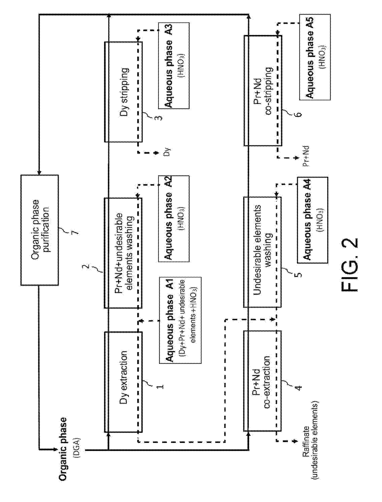
[0114]Now, reference is made to FIG. 2 which illustrates the principle of a first preferred embodiment of the second method of the invention, in which this method is designed for processing at an industrial scale, an acid aqueous phase A1 similar to the one treated in the Example 1 hereinbefore but with view to selectively recovering, not only the dysprosium but also the praseodymium and neodymium, and this, in two cycles, i.e.: a first cycle which aims at selectively recovering dysprosium present in the aqueous phase A1 and a second cycle which itself aims at selectively recovering praseodymium and neodymium present in the raffinate of the first cycle.

[0115]The first cycle comprises:[0116]a first step, designated as “Dy extraction” in FIG. 2, which aims at extracting dysprosium from the aqueous phase A1 by means of a first organic phase not miscible with water;[0117]a second step, designated as “Pr+Nd+undes...

example 3

Scheme of a Second Preferred Embodiment of the Second Method of the Invention

[0132]Reference is made now to FIG. 3 which illustrates the principle of a second preferred embodiment of the second method of the invention, wherein this method is also designed for selectively recovering and at an industrial scale dysprosium, praseodymium and neodymium from an acid aqueous phase A1 similar to the one processed in Example 1 hereinbefore but in a single cycle.

[0133]This cycle comprises:[0134]a first step, designated as “Dy+Pr+Nd co-extraction” in FIG. 3, which aims at co-extracting dysprosium, praseodymium and neodymium from the aqueous phase A1 by means of a first organic phase not miscible with water;[0135]a second step, designated as “Undesirable elements washing” in FIG. 3, which aims at washing the organic phase stemming from the “Dy+Pr+Nd co-extraction” by means of an acid aqueous phase A2 for removing from this organic phase the metal elements other than dysprosium, praseodymium and ...


PUM

PropertyMeasurementUnit
atomic numberaaaaaaaaaa
concentrationaaaaaaaaaa

Abstract

The invention relates to a hydrometallurgical process which makes it possible to selectively recover at least one “heavy” rare earth metal, i.e. a rare earth metal with an atomic number at least equal to 62, that is in an acidic aqueous phase resulting from the treatment of spent or scrapped permanent magnets. It also relates to a hydrometallurgical process which makes it possible to selectively recover, on the one hand, at least one heavy rare earth metal present in an acidic aqueous phase resulting from the treatment of spent or scrapped permanent magnets and, on the other hand, at least one “light” rare earth metal, i.e. a rare earth metal with an atomic number at most equal to 61, that is also in this acidic aqueous phase. The invention has in particular an application in the recycling of rare earth metals present in spent or scrapped permanent magnets of the type Neodymium-Iron-Boron (or NdFeB) and, in particular, dysprosium, praseodymium and neodymium, and also in the recycling of samarium present in spent or scrapped permanent magnets of the type samarium-cobalt (or SmCo).

Description

TECHNICAL FIELD[0001]The invention relates to the field for recovering rare earth metals present in spent or scrapped permanent magnets with view to recycling these rare earth metals.[0002]More specifically, the invention relates to a hydrometallurgical method giving the possibility of selectively recovering at least one “heavy” rare earth metal, i.e. with an atomic number at least equal to 62 (samarium, europium, gadolinium, terbium, dysprosium, holmium, erbium, thulium and / or ytterbium), found in an acid aqueous phase stemming from the processing of spent or scrapped permanent magnets.[0003]It also relates to a hydrometallurgical method giving the possibility of selectively recovering not only at least one heavy rare earth metal present in an acid aqueous phase stemming from the processing of spent or scrapped permanent magnets, but also at least one “light” rare earth metal, i.e. with an atomic number at most equal to 61 (scandium, yttrium, lanthanum, cerium, praseodymium and / or ...

Claims


Application Information

Patent Timeline
Patent Type & Authority Applications(United States)
IPC IPC(8): C01F17/00C22B7/00C22B59/00C22B3/28C01F17/17
CPCC01F17/0006C01F17/0075C22B59/00C22B7/007C22B3/0012C01P2006/80Y02P10/20C01F17/17C22B3/26C22B60/0239C22B60/0226C22B60/026C01F17/276C22B3/282
Inventor MIGUIRDITCHIAN, MANUELHAQUIN, VICTORPACARY, VINCENTLAUCOURNET, RICHARDMONTUIR, MARC
Owner COMMISSARIAT A LENERGIE ATOMIQUE ET AUX ENERGIES ALTERNATIVES
Why Eureka
Try Eureka