System for optical wireless power supply

a wireless power supply and wireless technology, applied in the field of wireless power supply systems, can solve the problems of increasing system costs and limited laser radiance of systems, and achieve the effect of reducing the small gain of the gain medium and lowering the radiance emitted

Active Publication Date: 2017-10-12
WI CHARGE
View PDF0 Cites 13 Cited by
  • Summary
  • Abstract
  • Description
  • Claims
  • Application Information

AI Technical Summary

Benefits of technology

[0034]Lasers with high radiance values are generally bigger and more complex, while lasers having lower radiance are typically smaller and simpler. The present system is limited in laser radiance because it typically uses an uncommon wavelength allowing for improved safety features, and small, low cost, high radiance lasers at such unconventional wavelengths are less commonly available and are likely to increase the cost of the system.
[0037]Opaque or even partially opaque materials can be easily detected when placed in the beam, by measuring the beam's attenuation. However some materials are transparent or nearly transparent and it is such transparent materials that are significantly harder to detect. There are two major groups of solid transparent materials, organic and inorganic materials. The number of inorganic transparent solid materials available to the general public is fairly limited, consisting mostly of glasses, a few semiconductor materials in common use, quartz, and some naturally occurring minerals such as diamonds, ruby and calcite. It is therefore possible to build a detection system for reflections from inorganic transparent materials, covering all likely scenarios.
[0052](c) a collimating lens, reducing the divergence of the light, and having a high radiant efficiency (>50%)
[0064](o) the thickness of the optical-to-electrical power converter active semiconductor layer is selected to be large enough to absorb most of the optical beam yet not so large that the quantum efficiency of the semiconductor layer becomes significantly reduced.
[0084]According to further implementations of the above described systems, at least one safety system is included, which estimates the probability of a breach of safety, given inputs from various sensors and monitors This is different from prior art systems, which provide actual measurement data only, such as the radar system in U.S. Pat. No. 6,407,535, with no indication of the probability of an error. The present system differs in that it provides a signal indicative of the probability of a breach of safety, as opposed to an actually detected breach of safety. This allows several significant advantages. Firstly, the system can react to potentially problematic situations, which become apparent by a low signal-to-noise, or a signal interruption, by differentiating between high risk situations and lower risk situations, and reacting differently to each situation. For instance, a low risk situation such as caused by a dirty aperture, by alignment faults, or similar occurrences, can be dealt with differently from a high risk situation, such as a high probability of beam intrusion, or an unreasonable beam power, whether high or low. Secondly, the system can combine probabilities from different safety systems into a unified probability, in order to achieve a sufficiently high detection accuracy. For example, if a system is designed to have a failure rate of 10-9 failures per hour, typically, in a changing environment, no single safety system can provide such reliable measurements without failure. However, a combination of safety systems can have better failure rate and if such data is combined with the probability of error, and if the statistical correlation of errors from both safety systems is known or can be estimated or approximated, then the data from the two systems may be combined to yield data with significantly higher probability. Such reliability data may be estimated, inter alia, from signal-to-noise, from the temperature of components, from preloaded data based on measurements on the same device or on a similar device, from user entered information, updated by the manufacturer or distributer or supplied by the user.
[0150]In many situations, it is necessary to limit the maximal power emitted by the system, to prevent exceeding some maximal value which may be derived from safety requirements of the system, from engineering requirements of the system, from the receiver's power requirements (which may dynamically change) or from other issues. In such a case, when the optical beam exceeds a certain power the system may reduce the small signal gain of the gain medium which will result in lowering of the radiance emitted by the system.

Problems solved by technology

One of the main challenges of wireless power transmission is building a safe, low cost, and small transmitter and receiver, which is nevertheless powerful (e.g. capable of transmitting significant levels of power).
The present system is limited in laser radiance because it typically uses an uncommon wavelength allowing for improved safety features, and small, low cost, high radiance lasers at such unconventional wavelengths are less commonly available and are likely to increase the cost of the system.

Method used


Image

  • System for optical wireless power supply
  • System for optical wireless power supply
  • System for optical wireless power supply

Examples


Embodiment Construction

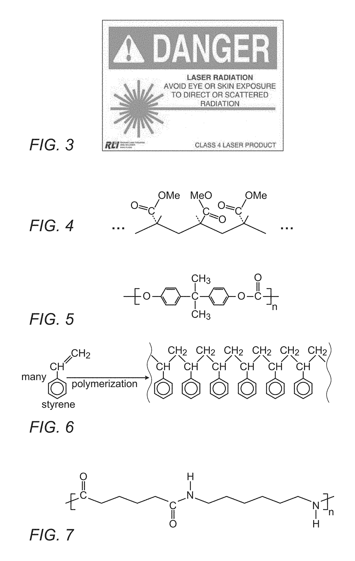
[0184]In view of the above described considerations, one exemplary implementation of the optical wireless power supply systems of the present disclosure could be a system tuned to work in between the first overtone of the C—H absorption at 6940 cm−1 and the second overtone of the C—H absorption at 8130 cm−1. Such overtone bands are less known bands, containing much less chemical information, and arise from essentially forbidden quantum mechanical transitions, and are only allowed due to complex mechanisms. Consequently, they provide wide, weak absorption bands, exactly as preferred for this application, but have found significantly less use in analytical chemistry. The broad nature of the bands allows for detecting various different polymer compositions, while the weak absorption allows the system to continue operation even in the vicinity of organic dirt and fingerprints. This makes these lines significantly less useful for typical uses of absorption measurements, but ideal for the...


PUM


Abstract

A system incorporating safety features, for optical power transmission to receivers, comprising an optical resonator having end reflectors and a gain medium, a driver supplying power to the gain medium, and controlling its small signal gain, a beam steering apparatus and a controller to control at least the beam steering apparatus and the driver. The controller responds to a safety risk occurring in the system, by outputting a command to change at least some of the small signal gain of the gain medium, the radiance of the optical beam, the power supplied by the driver, the scan speed or the scan direction and position of the beam steering apparatus, or to register the scan pose which defines the location of said optical-to-electrical power converter. The controller may also ensure a high overall radiance efficiency, and may warn of transmitted power not received by a targeted receiver.

Description

RELATED APPLICATIONS[0001]This application claims the benefit of U.S. Provisional Application No. 62 / 320,679, filed Apr. 11, 2016. This application is herein incorporated by reference in its entirety for all purposes.FIELD OF THE INVENTION[0002]The present invention relates to the field of wireless power beaming, especially as applied to use of a laser based transmission system to beam optical power in a domestic environment to a mobile electronic device.BACKGROUND OF THE INVENTION[0003]There exists a long felt need for the transmission of power to a remote location without the need for a physical wire connection. This need has become important in the last few decades, with the popularization of portable electronic devices operated by batteries, which need recharging periodically. Such mobile applications include mobile phones, laptops, cars, toys, wearable devices and hearing aids. Presently, the capacity of state of the art batteries and the typical battery use of a smart phone in...

Claims


Application Information

Patent Timeline
Patent Type & Authority Applications(United States)
IPC IPC(8): H02J50/30H02J7/35H01L31/0304H02J50/40H02J7/02
CPCH02J50/30H02J50/40H02J7/355H01L31/0304H02J7/025H04B10/807H02J7/35Y02E10/544H02J50/005H04B5/0037H02J50/90G01J1/4257H01S3/0014
Inventor SLEPOY, ALEXANDERGOLAN, LIORNAHMIAS, OMERSAGI, RANALPERT, ORTALMOR, ORI REFAEL
Owner WI CHARGE
Why Eureka
Try Eureka