
Method for preparing aqueous mno2 ink and capacitive energy storage devices comprising mno2

a capacitive energy storage and manganese dioxide technology, applied in hybrid capacitor electrodes, hybrid capacitor electrolytes, hybrid/edl manufacture, etc., can solve the problem of unmet demand for sc devices

Active Publication Date: 2017-10-26
THE HONG KONG POLYTECHNIC UNIV
View PDF2 Cites 15 Cited by
  • Summary
  • Abstract
  • Description
  • Claims
  • Application Information

AI Technical Summary

Benefits of technology

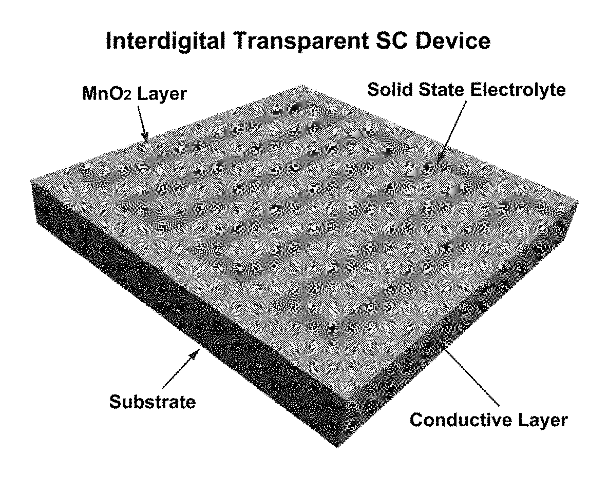
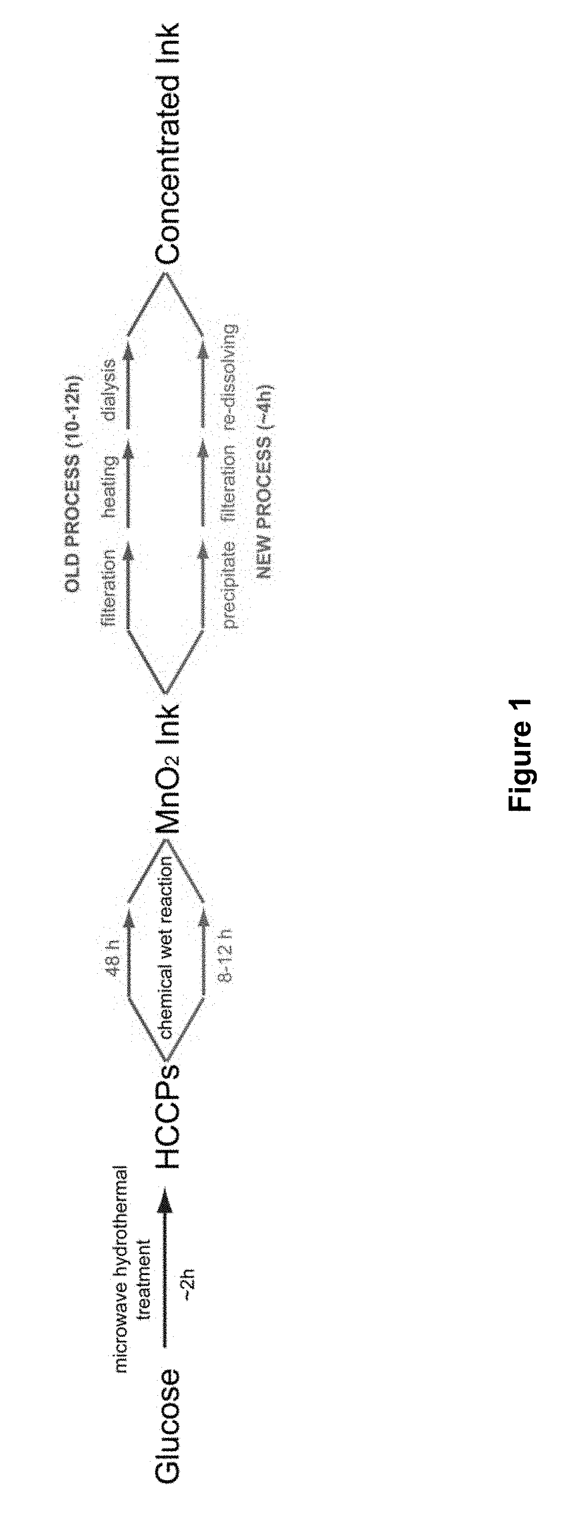
The patent text describes a method for making a MnO2 ink that can be used to create a symmetric supercapacitor device. The method involves mixing highly crystalline carbon particles with a KMnO4 solution and then increasing the temperature to precipitate MnO2. The resulting suspension can be diluted and redissolved to obtain a desired concentration. The method also involves coating electrodes with the MnO2 ink and using a solid state ionic liquid as an electrolyte. The resulting device can exhibit high performance and transparency. Another aspect of the patent text describes an interdigital transparent supercapacitor device that uses aqueous MnO2 ink.

Problems solved by technology

There is currently an unmet demand for SC devices have such characteristics.

Method used


Image

  • Method for preparing aqueous mno2 ink and capacitive energy storage devices comprising mno2
  • Method for preparing aqueous mno2 ink and capacitive energy storage devices comprising mno2
  • Method for preparing aqueous mno2 ink and capacitive energy storage devices comprising mno2

Examples


example 1

on of MnO2 Ink and Characterization

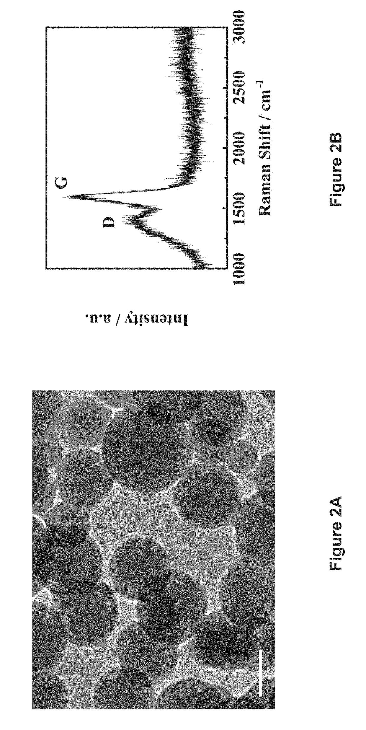
[0064]A glass tube filled with 10 wt % glucose solution was irradiated with a microwave system as described in L. Tang et al. (ACS Nano 2012, 6, 5102-5110) at 350 psi and 250° C. for 5 min, to form a suspension containing highly crystalline carbon particles (HCCPs). The suspension was poured out for filtration. The HCCPs residues were re-dissolved into water and sonicated to form a 0.1 mg·mL−1 HCCPs suspension. Subsequently, 16 mg·mL−1 KMnO4 solution was added into the HCCPs suspension dropwise under continuous stirring and maintained at 45° C. for 9 h. The resultant suspension was then heated to 75° C. under stirring for 1 h. After cooling to room temperature, the suspension was filtered by using filter paper (pore size: 15-20 μm) to remove the excess reactants to obtain a MnO2 ink. Pure ethanol was added to the as-obtained MnO2 ink until precipitates were observed. The MnO2 suspension was centrifuged at 4000 rpm, followed by vacuum filtration usi...

example 2

on of Electrochemical Performance of MnO2 Symmetric Supercapacitor with Ionic Liquids

[0070](“CE” represents Comparative Experimental Example)

Preparation of SCNTs Paper (“CE-A”)

[0071]As a first step, an ink is formed by allowing CNTs grown by laser ablation and sodium dodecylbenzenesulfonate (SDBS, Sigma-Aldrich) to be dispersed in deionized water. Their concentrations were 10 and 1-5 mg / mL, respectively. After bath sonication for 5 min, the CNT dispersion was probe-sonicated for 30 min at 200 W (VC 505; Sonics) to form an ink. Meyer rods (Rdspecialties) were used to coat the CNT ink onto Xerox paper. Subsequently, conductive paper is prepared as follows. For Meyer rod coating of CNT films, CNT ink was dropped onto the paper surface. Then, the rod was rolled to the other end of the paper (Xerox). The thickness of the dried CNT film could be controlled by the ink concentration and the wire size of the Meyer rods.

Preparation of Graphene / MnO2 Composite (“CE-B”)

[0072]Ni foam was used to ...


PUM


Abstract

In one aspect, the present disclosure relates to an improved method of preparing concentrated MnO2 ink with increased efficiency and cost effectiveness. The method involves mixing KMnO4 solution with highly crystalline carbon particles (HCCPs) with average diameters less than 800 nm at 30-60° C. for at least 8 hours. The present disclosure further relates to a symmetric supercapacitor device comprising MnO2 coated electrodes and a solid state ionic liquid as electrolyte, as well as an interdigital transparent SC (IT-SC) device comprising aqueous MnO2 ink.

Description

FIELD[0001]The present disclosure generally relates to the preparation of an aqueous manganese dioxide (MnO2) ink and MnO2 ink based capacitive energy storage devices, with improved electrochemical properties.BACKGROUND[0002]The use of printing technology is of great interest in the various areas ranging from thin film transistors (TFTs), energy storage devices, solar cells to micro electro-mechanical system (MEMS). In this wide variety of applications, preparations of various inks comprising semiconductors, biological materials, carbon, and conductive oxides have been reported.[0003]One exemplary potential candidate for use as ink in such printing technology in view of its abundance, high theoretical capacity and environmental compatibility is manganese dioxide (MnO2).[0004]MnO2 is usually regarded as an ideal candidate for the electrode materials of portable devices, water treatment, up-conversion as well as photocatalysis.[0005]Conventional MnO2 electrodes are mainly prepared by ...

Claims


Application Information

Patent Timeline
Patent Type & Authority Applications(United States)
IPC IPC(8): H01G11/46H01G11/62H01G11/64H01G11/86
CPCH01G11/46H01G11/62H01G11/64H01G11/86
Inventor QIAN, JIASHENGYUAN, JIKANGLAU, SHU PING
Owner THE HONG KONG POLYTECHNIC UNIV
Learn More