Solid electrolyte separator bonding agent

a solid electrolyte separator and bonding agent technology, applied in the manufacture of secondary cells, cell components, cell component details, etc., can solve the problems of chemical incompatibility with lithium metal negative electrodes, liquid electrolytes suffer, outgassing at high voltage, etc., and achieve the effect of lowering the interfacial impedan

Inactive Publication Date: 2017-11-16
QUANTUMSCAPE CORP
View PDF6 Cites 53 Cited by
  • Summary
  • Abstract
  • Description
  • Claims
  • Application Information

AI Technical Summary

Benefits of technology

[0007]In one embodiment, the instant disclosure sets forth an electrochemical stack which includes a lithium metal (Li) negative electrode, a positive electrode, an electrolyte separator in direct contact with the Li metal negative electrode, and a bonding layer comprising a lithium salt, a polymer, and a solvent. In some examples, the bonding layer is a gel electrolyte. The bonding layer directly contacts, and is positioned between, the electrolyte separator and the positive electrode, and the electrolyte separator protects the Li metal negative electrode from exposure to the polymer or to the solvent, or both, in the bonding layer. As described herein, ...

Problems solved by technology

However, liquid electrolytes suffer from several problems including flammability during thermal runaway, outgassing at high voltages, and chemical incompatibility with lithium metal negative electrodes.
Despite these advantages, solid electrolytes are still insufficient in several regards for commercial applications.
Moreover, even in the absence of delamination, solid interfaces tend not to perfectly align with each other.
If a solid lithium metal negative electrode is laminated to a solid electrolyte, and the solid electrolyte (i.e., separator), on the opposing side, is laminated to a positive electrode, each solid interface (Li-separator & Separator-Cathode) may have insufficient electrical contact due to areas where one solid interface does not perfectly align and contact another solid interface.
Areas of non-contact between the solid electrolyte and the positive electrode result in impedance rises which reduce a battery's power and capacity.
To date and the best of Applicant's knowledge, there are no public disclosures of commercially viable solid electrolyte separators which interface with a solid positive electrode with a sufficient...

Method used


Image

  • Solid electrolyte separator bonding agent
  • Solid electrolyte separator bonding agent
  • Solid electrolyte separator bonding agent

Examples


example 1

Electrochemical Stack Having a Bonding Layer

[0248]In this example, a free standing gel electrolyte film was first prepared.

[0249]A blend of ethylene carbonate (EC) and propylene carbonate (PC) solvents was prepared in a 1:1 w / w ratio. The lithium salt lithium hexafluorophosphate was added to this mixture to achieve a 1M solution. To form the gel solution, 0.8 grams of a PVDF-HFP polymer (Kynar 2801) was mixed 2.8 grams of the lithium hexafluorophosphate solution and 8.5 grams of a solvent, THF (Tetrahydrofuran). The solution was cast via doctor blade onto a glass substrate inside a glove box. The film was allowed to dry in the glove box for 4 hours. The dry film thickness was 45 μm. This dry film was used as the gel electrolyte 103 below.

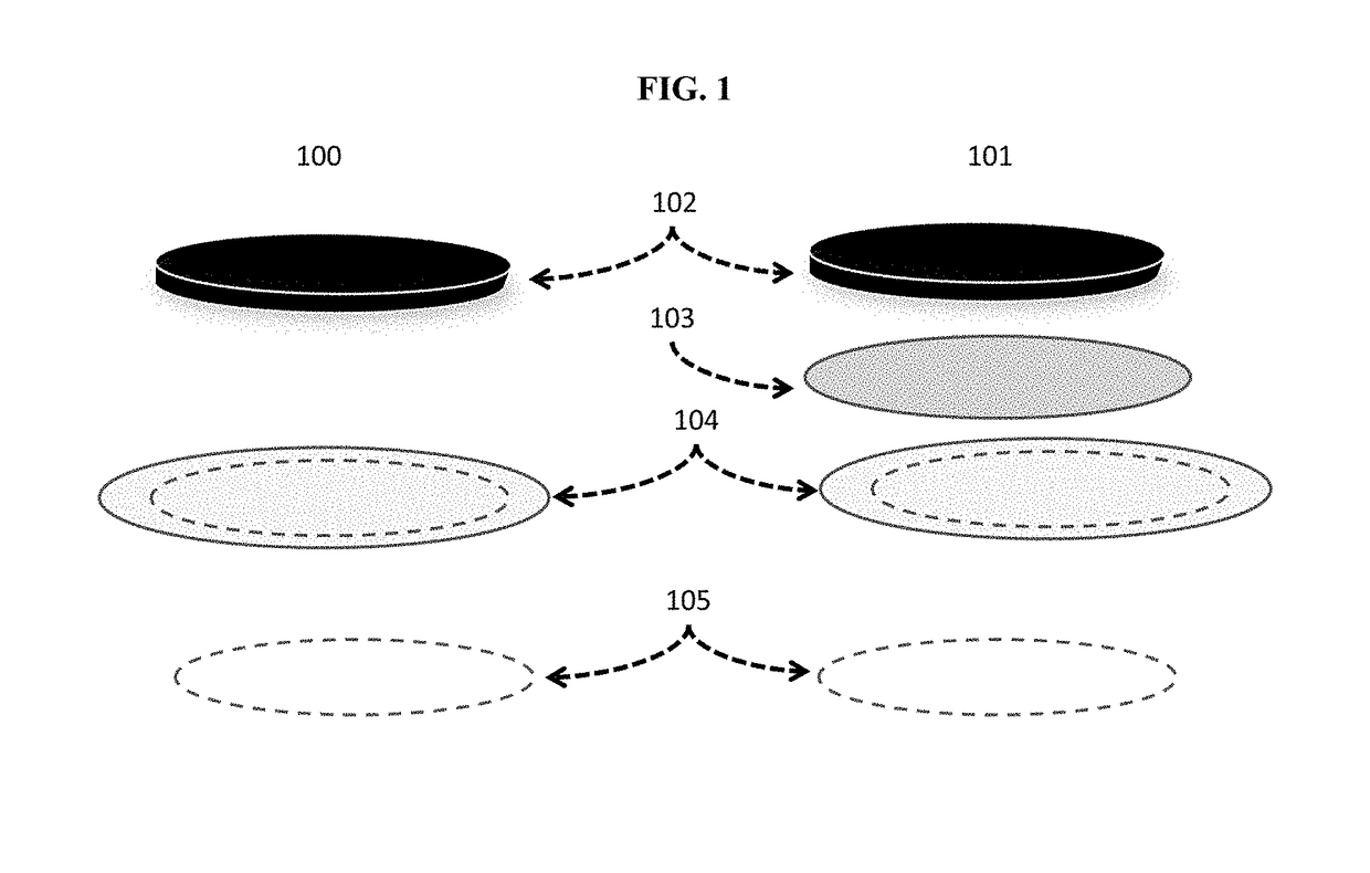
[0250]As shown in FIG. 1, two electrochemical stacks were prepared. The layers were pressed together in the actual electrochemical stack, but in FIG. 1 the layers are separated for illustrative purposes.

[0251]In one example, 100, the electrochemical...

example 3

Spin Coated Gel Bonding Layer

[0256]A blend of ethylene carbonate (EC) and propylene carbonate (PC) solvents was prepared in a 1:1 w / w ratio. The lithium salt, LiPF6, was added to this mixture to achieve a 1M solution. PAN polymer was mixed with the solution in a measured volume ratio PAN to EC:PC. The solution was spin-cast using a Laurel Technologies, Spincoater for up to 60 seconds to form a film. By varying the spin-cast RPM(s), thicker or thinner free standing films were prepared. The film was allowed to dry at room temperature on a garnet substrate for twenty-four hours. FIG. 4 shows the thickness of a PAN-containing film, which is as a function of the spin-cast RPM. The scale bar in FIG. 4 is 5 μm. Higher RPM results in thinner films. FIG. 5 shows a 47.4% PAN gel electrolyte which was spin-cast at 2000 RPM. The gel electrolyte, 501, is positioned on top of the garnet separator, 502. The scale bar in FIG. 5 is 100 μm.

example 4

ndividual Electrochemical Layers with Spin Coated Gel Bonding Layer

[0257]Determination of the interfacial resistance between a bonding layer and a garnet electrolyte requires measurement of a full cell resistance and subtraction of all other resistance components. The following experiments are used to determine the resistance of each layer and interface in a full cell so as to enable calculation of the interfacial resistance between a gel and a garnet separator (ASRB-G). As shown in FIG. 6, an electrochemical stack was provided having Li metal 603, a solid lithium-stuffed garnet, 602, Li7La3Zr2O12Al2O3, 50 μm thick film, and a lithium metal electrode, 601. This configuration is referred to a symmetric cell Li|garnet|Li cell.

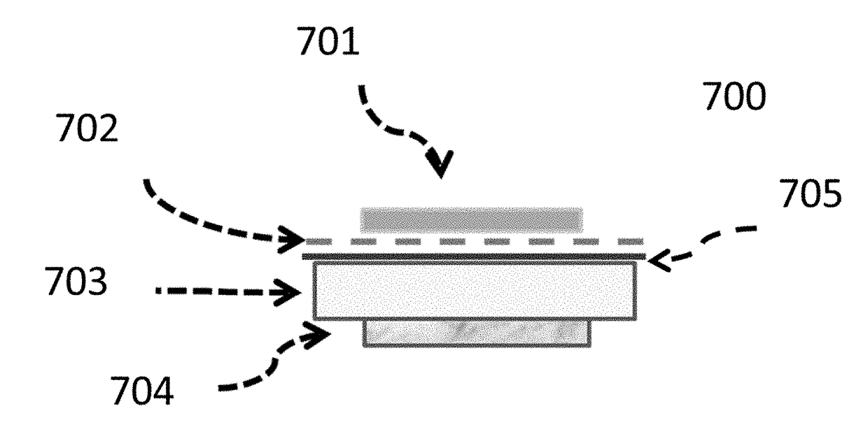
[0258]FIG. 7 shows a stack consisting of Li|Garnet|scGel|fsGel|Li-foil which was constructed and measured. Here, scGel refers to the spin-coat prepared gel electrolyte layer, 705 and fsGel refers to the doctor-blade coated free standing gel electrolyte layer, 702...


PUM


Abstract

Set forth herein are electrochemical cells which include a negative electrode current collector, a lithium metal negative electrode, an oxide electrolyte membrane, a bonding agent layer, a positive electrode, and a positive electrode current collector. The bonding agent layer advantageously lowers the interfacial impedance of the oxide electrolyte at least at the positive electrode interface and also optionally acts as an adhesive between the solid electrolyte separator and the positive electrode interface. Also set forth herein are methods of making these bonding agent layers including, but not limited to, methods of preparing and depositing precursor solutions which form these bonding agent layers. Set forth herein, additionally, are methods of using these electrochemical cells.

Description

BACKGROUND[0001]This application claims priority to, and the benefit of, US Provisional Patent Application No. 62 / 336,474, filed, May 13, 2016, entitled SOLID ELECTROLYTE SEPARATOR BONDING AGENT, and US Provisional Patent Application No. 62 / 448,294, filed Jan. 19, 2017, entitled SOLID ELECTROLYTE SEPARATOR BONDING AGENT, the entire contents of each of which are herein incorporated by reference in their entirety for all purposes.[0002]In a rechargeable Li+ ion battery, Li+ ions move from a negative electrode to a positive electrode during discharge and in the opposite direction during charge. This process produces electrical energy (Energy=Voltage×Current) in a circuit connecting the electrodes, which is electrically insulated from, but parallel to, the Li+ ion conduction path. The battery's voltage (V versus Li) is a function of the chemical potential difference for Li situated in the positive electrode as compared to the negative electrode and is maximized when Li metal is used as ...

Claims


Application Information

Patent Timeline
IPC IPC(8): H01M2/16H01M4/1399H01M4/137H01M10/04H01M10/052H01M10/0583H01M4/02H01M50/414H01M50/489
CPCH01M2/168H01M4/137H01M10/052H01M4/1399H01M10/0583H01M10/0468H01M2300/0071H01M2004/027H01M4/382H01M10/0562H01M50/461H01M50/414H01M50/489Y02E60/10H01M10/0565H01M50/411
Inventor CHEN, ZHEBODONNELLY, NIALLHOLME, TIMSINGH, DEEPIKA
Owner QUANTUMSCAPE CORP
Why Eureka
Try Eureka