Etching process method

a technology of etching process and etching gas, which is applied in the direction of electrical equipment, basic electric elements, electric discharge tubes, etc., can solve the problems of process conditions that may not be suitable for selected etching gas, and achieve the effect of suppressing side etching and high etching ra

Active Publication Date: 2017-12-28
TOKYO ELECTRON LTD
View PDF9 Cites 17 Cited by
  • Summary
  • Abstract
  • Description
  • Claims
  • Application Information

AI Technical Summary

Benefits of technology

[0007]One aspect of the present invention is directed to providing an etching process method that is capable of maintaining a high etch rate while suppressing side etching.

Problems solved by technology

However, in the above-described etching techniques, the etching gas and process conditions are selected in view of increasing mask selectivity but not in view of suppressing side etching and obtaining a desirable etching profile.
As such, the selected etching gas and process conditions may not be appropriate for suppressing side etching and obtaining a desirable etching profile.

Method used


Image

  • Etching process method
  • Etching process method
  • Etching process method

Examples


first embodiment

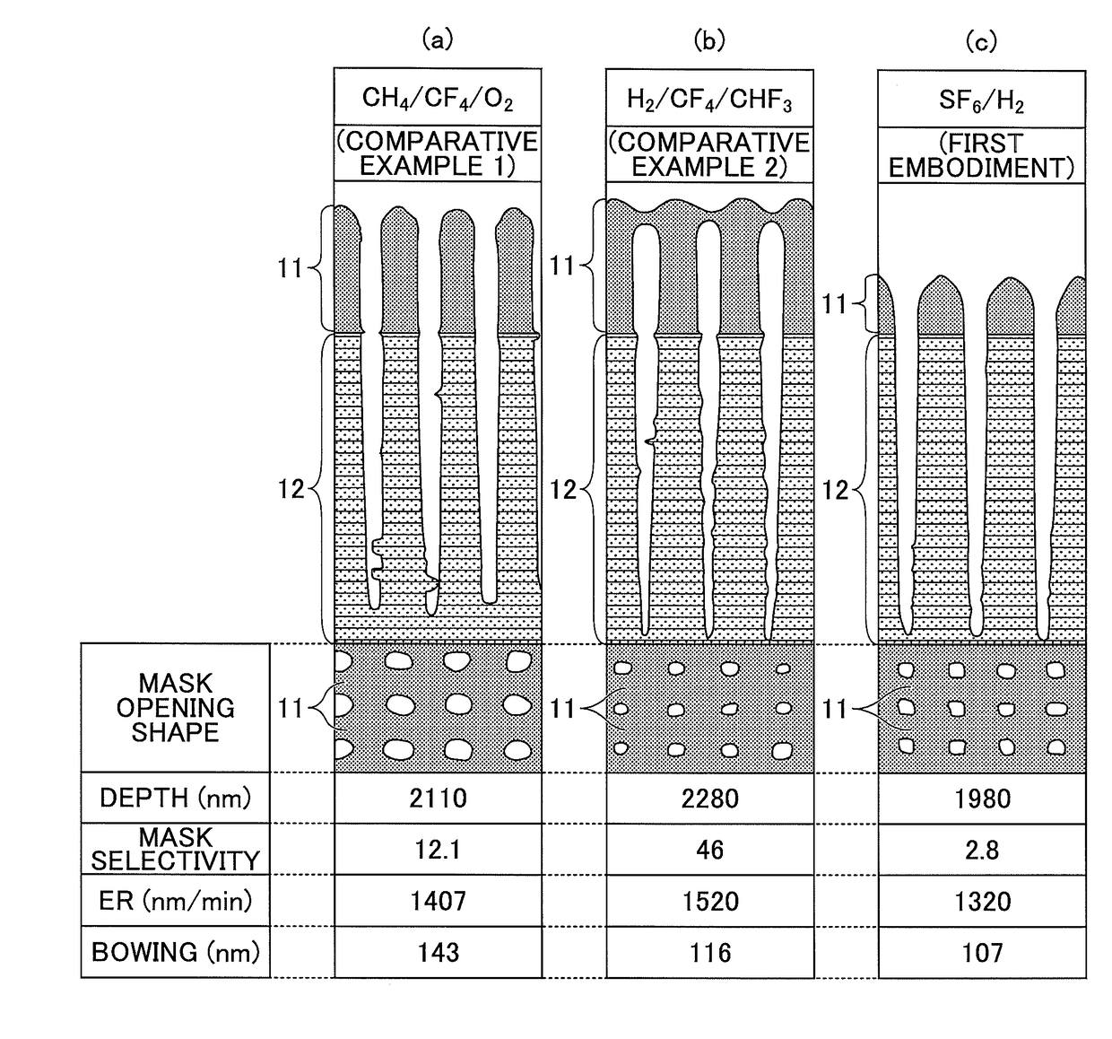
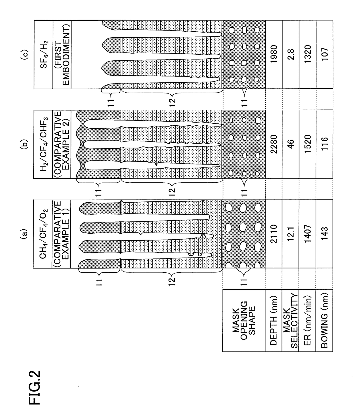
[0041]In the first embodiment of the present invention, the laminated film 12 is etched under the following process conditions.

[0042]Process Condition (First Embodiment)

Wafer Temperature −40° C. or lower (Chiller Temperature: −60° C.) Gas SF6 (sulfur hexafluoride) / H2 (hydrogen) First High Frequency 2500 W, continuous wave Power HF Second High Frequency 4000 W, continuous wave Power LF Processing Chamber 15 to 25 mTorr (2.0 to 3.3 Pa) Internal Pressure

[0043]Note that in the first embodiment and further embodiments of the present invention described below, the first high frequency power HF and the second high frequency power LF are applied. However, the present invention is not limited thereto, and in some embodiments, only the first high frequency power HF may be applied, for example.

[0044]In FIG. 2, (c) shows an example etching result of performing the etching process according to the first embodiment. By comparing the etching result (c) of the first embodiment with the etching resu...

second embodiment

[0051]In the second embodiment, an etching process is performed on the laminated film 12 under the following process conditions.

[0052]Process Conditions (Second Embodiment)

Wafer Temperature −40° C. or lower (Chiller Temperature: −60° C.) Gas SF6 (sulfur hexafluoride) / CH4 (methane) First High Frequency2500 W, continuous wave Power HF Second High Frequency 4000 W, continuous wave Power LF Processing Chamber 15 to 25 mTorr (2.0 to 3.3 Pa) Internal Pressure

[0053]In FIG. 3, (c) shows an example etching result of performing the etching process according to the second embodiment. Note that (a) and (b) of FIG. 3 correspond to the same etching results of Comparative Examples 1 and 2 that are shown in FIG. 2. By comparing the etching result (c) of the etching process according to the second embodiment shown in FIG. 3 with the etching results (a) and (b) of Comparative Examples 1 and 2 of FIG. 3, it can be appreciated that in the etching process according to the second embodiment, side etching...


PUM


Abstract

An etching process method is provided that includes outputting a first high frequency power from a first high frequency power supply in a cryogenic temperature environment where the temperature of a substrate is controlled to be less than or equal to −35° C., supplying a sulfur fluoride-containing gas and a hydrogen-containing gas, generating a plasma from the supplied sulfur fluoride-containing gas and hydrogen-containing gas, and etching a laminated film made up of laminated layers of silicon-containing films having different compositions with the generated plasma.

Description

CROSS-REFERENCE TO RELATED APPLICATION[0001]The present application is based on and claims the benefit of priority to Japanese Patent Application No. 2016-124600 filed on Jun. 23, 2016, the entire contents of which are hereby incorporated by reference.BACKGROUND OF THE INVENTION1. Field of the Invention[0002]The present invention relates to an etching process method.2. Description of the Related Art[0003]Techniques for etching a silicon-containing film using a fluorocarbon-based (CF-based) gas are known. Further, techniques for increasing mask selectivity with respect to a silicon-containing film by adding a hydrocarbon-based (CH-based) gas to an etching gas are known.[0004]Also, techniques for increasing mask selectivity with respect to a silicon-containing film using a fluorinated sulfur-containing gas instead of a fluorocarbon-based gas are known (see, e.g., Japanese Unexamined Patent Publication No. H04-84427 and Japanese Unexamined Patent Publication No. 2005-72518).[0005]Howev...

Claims


Application Information

Patent Timeline
Patent Type & Authority Applications(United States)
IPC IPC(8): H01L21/311H01L21/02H01L21/67H01J37/32
CPCH01L21/31116H01L21/022H01L21/67248H01L21/67069H01J37/32091H01J2237/334H01J37/32816H01J37/32724H01J37/32642H01J37/32834H01J2237/2001H01J37/3244H01J37/32165H01L21/3065H01L21/324H01L21/32136
Inventor KUDO, JINTAKAYAMA, WATARUTOMURA, MAJU
Owner TOKYO ELECTRON LTD
Why Eureka
Try Eureka