Method and apparatus for detecting ground faults in inverter outputs on a shared DC bus

Active Publication Date: 2017-12-28
ROCKWELL AUTOMATION TECH
View PDF1 Cites 20 Cited by
  • Summary
  • Abstract
  • Description
  • Claims
  • Application Information

AI Technical Summary

Benefits of technology

[0009]A fault detection circuit may be included that generates a signal corresponding to current flowing on the DC bus and through one of the freewheeling diodes when the low voltage is applied to the DC bus. The signal is transmitted back to a controller configured to open and close an AC contactor connected in series between the input power and the rectifier section. If the signal indicates a ground fault is present at the output of one of the inverter sections, the controller keeps the contactor open, preventing the AC voltage from being applied to the rectifier section, which otherwise would supply full DC bus voltage on the DC bus resulting in equipment damage. If the signal indicates no ground fault at the output of the inverter sections, the controller closes the contactor and allows the motor drive system to complete its power up sequence.
[0010]According to one embodiment of the invention, a system to detect a ground fault at an output of an inverter is disclosed, where the inverter is connected to a DC bus. The system includes a power supply, a fault detection circuit, and a control circuit. The power supply is operable to provide a test voltage on the DC bus, where the test voltage is less than half of a minimum DC bus operating voltage. The fault detection circuit is operatively connected to the DC bus to generate a fault signal responsive to applying the test voltage on the DC bus when the ground fault is present at the output of the inverter. The control circuit is operable to delay a normal DC bus operating voltage from being applied to the DC bus while the test voltage is provided to the DC bus, detect the fault signal, and prevent the normal DC bus operating voltage from being applied to the DC bus when the fault signal is detected.
[0011]According to another embodiment of th

Problems solved by technology

If the signal indicates a ground fault is present at the output of one of the inverter sections, the controller keeps the contactor open, preventing th

Method used


Image

  • Method and apparatus for detecting ground faults in inverter outputs on a shared DC bus
  • Method and apparatus for detecting ground faults in inverter outputs on a shared DC bus
  • Method and apparatus for detecting ground faults in inverter outputs on a shared DC bus

Examples


Embodiment Construction

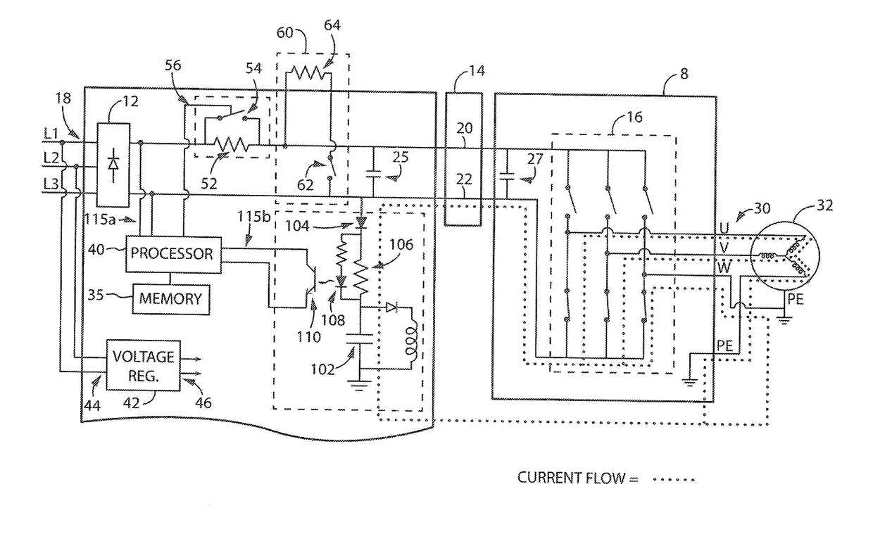
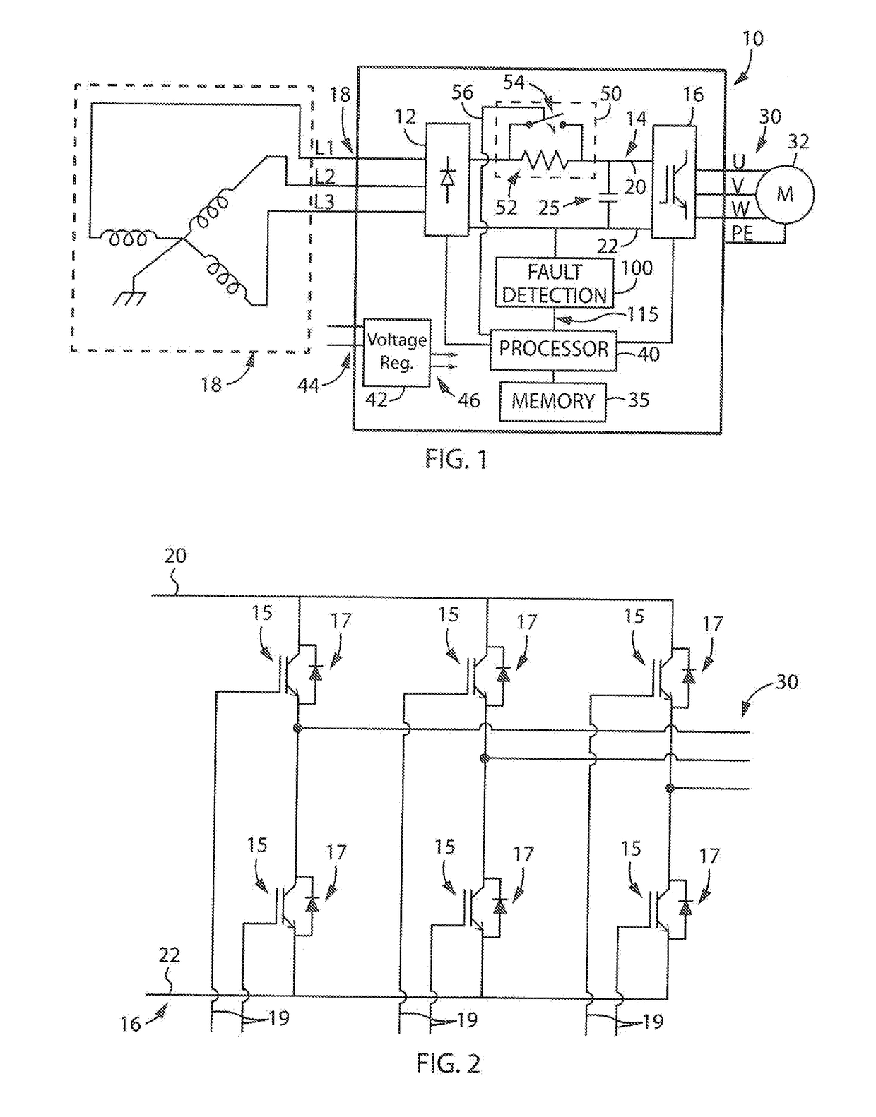
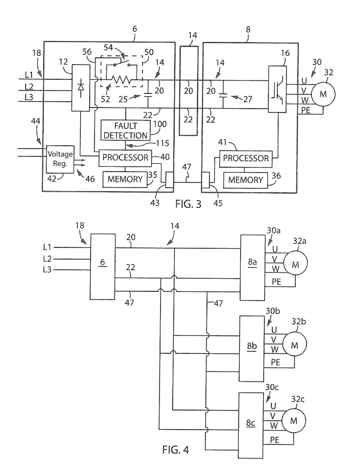
[0024]Turning initially to FIG. 1, a common topology for an Adjustable Speed Drive (ASD) 10 incorporating one embodiment of the invention is illustrated. The ASD 10 includes a rectifier section 12, a DC bus section 14, and an inverter section 16. The ASD 10 receives a three-phase AC input voltage 18 into the rectifier section 12. The rectifier section 12 may include passive or active rectification, for example diodes, thyristors, silicon controlled rectifiers, or transistors as is known in the art, to convert the three-phase AC input voltages into a DC voltage. The DC voltage is present between the positive rail 20 and the negative rail 22 of the DC bus section 14. Typical DC voltages may be a positive or negative 650 volts for a common 460 volt, three-phase AC input voltage. To maintain a stiff DC voltage on each of the positive and negative bus rails, 20 and 22, a DC bus capacitor 25 is included between the rails 20 and 22, where a stiff DC voltage remains approximately equal to t...


PUM


Abstract

A system to detect a ground fault at the output of an inverter section prior to powering up a motor drive system is disclosed. A low voltage power supply is connected to the DC bus prior to connecting the input power source to the rectifier section. If a ground fault exists, the voltage potential on the DC bus causes conduction through one of the freewheeling diodes connected in parallel to the power switching device on the output of the inverter section. A fault detection circuit generates a signal corresponding to the presence of the low Voltage potential when the low voltage is applied to the DC bus. If a ground fault is present at the output of one of the inverter sections, the motor drive system prevents the AC voltage from being applied to the rectifier section.

Description

BACKGROUND OF THE INVENTION[0001]The subject matter disclosed herein relates generally to detecting fault conditions in a motor drive and, more specifically, to detecting a ground fault in a motor drive system.[0002]Common AC motors use three-phase electrical power connected to the stator windings of a motor to run the motor. Each stator winding is connected to a different conductor from a three-phase power source, in which each conductor delivers a different phase of the electrical power to the motor. The three-phase power source may be a direct connection to line power, but more commonly, the motor is connected to an adjustable speed motor drive (ASD). The ASD allows for speed control of the motor not available by connecting the motor directly to line power.[0003]As is known in the art, there are many electrical topologies for ASDs used to convert the fixed voltage and frequency from the line input into a controlled voltage and frequency output for a three-phase motor. One common ...

Claims


Application Information

Patent Timeline
IPC IPC(8): H02P29/024H02P27/06H02M1/32G01R31/42H02M7/537G01R31/02G05B19/042
CPCH02P29/024H02M7/537H02M1/32G05B19/0425G01R31/025G01R31/42H02P27/06G01R31/34G01R31/52H02M7/5387H02P29/0241H02M1/008
Inventor FIGIE, JOHN R.VRANKOVIC, ZORANGRIES, MARK A.WINTERHALTER, CRAIGSIZOV, GENNADI
Owner ROCKWELL AUTOMATION TECH
Why Eureka
Try Eureka