Manufacturing method for gas cell, manufacturing method for magnetic field measurement apparatus, and gas cell

a manufacturing method and gas cell technology, applied in the direction of magnetic field measurement using magneto-optic devices, instruments, apparatus using atomic clocks, etc., can solve the problems of increasing the number of steps, difficult handling, and the amount of disposed paraffin in the disposing step may vary, so as to prevent impurities

Active Publication Date: 2018-01-04
SEIKO EPSON CORP
View PDF1 Cites 5 Cited by
  • Summary
  • Abstract
  • Description
  • Claims
  • Application Information

AI Technical Summary

Benefits of technology

[0007]According to the manufacturing method of this application example, in the disposing of the holding member, since the coating material is handled in a state of being included in the holding member, an amount of the coating material can be easily adjusted to a desired amount on the basis of a length of the holding member, and the coating material can also be easily disposed in the second chamber, compared with a case where only the coating material is handled. It is possible to reduce a variation in an amount of the coating material disposed in each cell by managing the length of the holding member (reducing a variation in the length thereof). Thus, in the forming of the film, it is possible to stably form a film of the coating material with a desired film thickness on the inner wall of the cell, and also to minimize a variation in a thickness of a formed film of the coating material between individuals. Consequently, it is possible to stably and efficiently manufacture the gas cell by reducing deterioration in quality (sensitivity, measurement accuracy, or the like) or reducing differences between qualities of individuals.Application Example 2
[0009]According to the manufacturing method of this application example, since the holding member is made of the heat-resistive material, it is possible to prevent degradation of the holding member due to heat or generation of a gas from the holding member when the holding member is heated in the heating of the holding member. Consequently, it is possible to prevent deterioration in quality (sensitivity, measurement accuracy, or the like) of the gas cell caused by degradation of the holding member or mixing of a gas from the holding member.Application Example 3
[0017]According to the manufacturing method of this application example, the solid containing the alkali metal is disposed in the second chamber and is sealed along with the holding member including the coating material, a film of the coating material is formed on the inner wall of the cell, and then an alkali metal gas is generated from the solid after the film of the coating material is formed. Thus, the formed film of coating material can prevent or reduce a change in a behavior when excited alkali metal atoms directly collide with the inner wall of the cell. It is possible to reduce the number of sealing steps to one, and thus to prevent impurities from entering the second chamber from the outside after the film of the coating material is formed, compared with a case where the cell is temporarily sealed, the temporary sealing is removed after a film of the coating material is formed on the inner wall, and the solid containing the alkali metal is disposed in the second chamber and is then sealed.Application Example 7
[0021]According to the configuration of this application example, if the holding member including the coating material disposed in the second chamber is heated, the coating material is vaporized in the cell, and then if the cell is cooled, a film of the coating material is formed on the inner wall of the cell. Therefore, it is possible to obtain the gas cell in which a layer of the coating material is formed on the inner wall of the cell. Here, since the coating material in a state of being included in the holding member can be handled when the coating material is disposed in the second chamber, an amount of the coating material can be easily adjusted on the basis of a length of the holding member, and the coating material can also be disposed in the second chamber, compared with a case where only the coating material is handled. Thus, by reducing differences between individuals, it is possible to more uniformly form a film of the coating material in the cell and also to reduce the number of steps due to handling of the coating material. Consequently, it is possible to efficiently obtain the gas cell with less variation in performance.Application Example 9
[0031]According to the configuration of this application example, if the solid containing the alkali metal disposed in the second chamber is vaporized after a film of the coating material is formed on the inner wall of the cell, it is possible to obtain the gas cell in which an alkali metal gas fills the cell of which a layer of the coating material is formed on the inner wall. Since the solid containing the alkali metal is disposed in the second chamber along with the holding member including the coating material in advance, it is possible to prevent impurities from entering the second chamber from the outside, compared with a case where the solid containing the alkali metal is disposed in the second chamber after a film of the coating material is formed on the inner wall of the cell.

Problems solved by technology

Paraffin which is appropriately used as a coating material is generally a soft solid (waxy) at the room temperature, and is thus hard to handle when an amount thereof is finely adjusted or the paraffin is disposed inside the cell.
Thus, there is concern that an amount of disposed paraffin may vary in a disposing step, or the number of steps may increase, but JP-A-2013-7720 does not disclose a method of handling or disposing a coating material.
If an amount of the coating material disposed inside the cell varies, a coating material film formed on the inner wall of the cell may not have a desired film thickness, and thicknesses of coating material films may be different from each other between individuals.
Thus, there is a problem in that quality (sensitivity, measurement accuracy, or the like) of a manufactured gas cell deteriorates, or differences between qualities of individuals occur.

Method used


Image

  • Manufacturing method for gas cell, manufacturing method for magnetic field measurement apparatus, and gas cell
  • Manufacturing method for gas cell, manufacturing method for magnetic field measurement apparatus, and gas cell
  • Manufacturing method for gas cell, manufacturing method for magnetic field measurement apparatus, and gas cell

Examples


modification example 1

[0122]A solid containing an alkali metal used to manufacture the gas cell according to the embodiment is not limited to the ampoule 20, and may have other forms. Modification Example 1 is different from the embodiment in that a solid containing an alkali metal has a form of a pill instead of an ampoule, but is substantially the same in terms of a configuration of a cell. With reference to FIGS. 11 and 12, a description will be made of configurations of a gas cell and a pill used for the gas cell related to Modification Example 1. Constituent elements common to the embodiment are given the same reference numerals, and description thereof will be omitted.

Configuration of Pill

[0123]First, a description will be made of a configuration of a pill as a solid containing an alkali metal related to Modification Example 1. FIG. 11 is a perspective view illustrating a pill related to Modification Example 1. As illustrated in FIG. 11, a pill 26 related to Modification Example 1 has, for example,...

modification example 2

[0131]An apparatus to which the gas cell according to the embodiment is applicable is not limited to the magnetic field measurement apparatus 100. The gas cells according to the embodiment and the modification example are applicable to an atomic oscillator such as an atomic clock. FIG. 13 is a schematic diagram illustrating a configuration of an atomic oscillator according to Modification Example 2. FIGS. 14A and 14B are diagrams for explaining an operation of the atomic oscillator according to Modification Example 2.

Atomic Oscillator

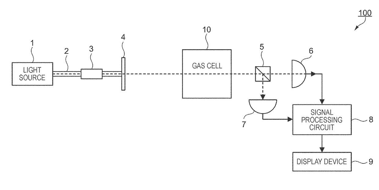
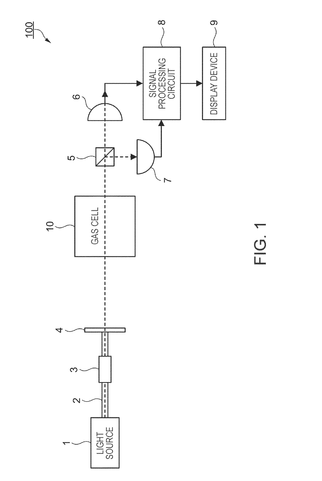
[0132]An atomic oscillator (quantum interference apparatus) 101 related to Modification Example 2 illustrated in FIG. 13 uses a quantum interference effect. As illustrated in FIG. 13, an atomic oscillator 101 includes the gas cell 10 (or the gas cell 50) according to the embodiment, a light source 71, optical components 72, 73, 74 and 75, a photodetector 76, a heater 77, a temperature sensor 78, a magnetic field generation unit 79, and a controller 80.

[...

modification example 3

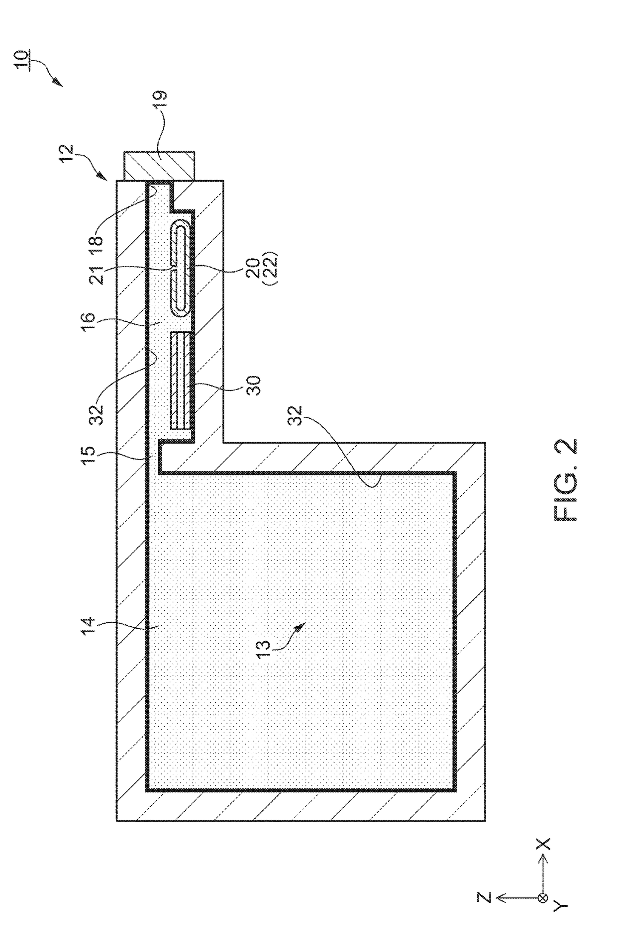
[0141]A gas cell of the embodiment of the invention is not limited to the gas cells 10 and 50 in a state of being completed according to the manufacturing method for the gas cell of the embodiment, and may be the gas cell 10A in a half-completed state. A description will be made of a configuration of the gas cell 10A in a half-completed state related to Modification Example 3 with reference to FIG. 7.

Configuration of Gas Cell

[0142]As illustrated in FIG. 7, the gas cell 10A in a half-completed state related to Modification Example 3 is in a state in which the processes up to the sealing step are performed in the embodiment. In other words, the opening 18 is sealed with the sealing member 19, and thus the cell 12 of the gas cell 10A is sealed, in a state in which the inside thereof is decompressed, and an amount of impurities is extremely small. In the sealed cell 12 (reservoir 16), the alkali metal solid 24 for generating the alkali metal gas 13 is disposed in the ampoule 20 in an se...


PUM

PropertyMeasurementUnit
melting pointaaaaaaaaaa
wavelengthaaaaaaaaaa
thicknessaaaaaaaaaa

Abstract

A manufacturing method for a gas cell includes disposing a holding member including a coating material in a reservoir of a cell having a main chamber, the reservoir communicating with the main chamber, and an opening provided in the reservoir, sealing the cell, heating the holding member so as to generate a vapor of the coating material in the cell, and cooling the cell so as to form a film of the coating material on an inner wall of the cell.

Description

BACKGROUND1. Technical Field[0001]The present invention relates to a manufacturing method for a gas cell, a manufacturing method for a magnetic field measurement apparatus, and a gas cell.2. Related Art[0002]There is an optical pumping magnetic field measurement apparatus which irradiates a gas cell in which an alkali metal gas is enclosed with linearly polarized light, and measures a magnetic field according to a rotation angle of a polarization plane (for example, refer to JP-A-2013-7720). JP-A-2013-7720 discloses a configuration of a gas cell and a manufacturing method therefor in which an alkali metal substance is accommodated in a cavity of a cell whose inner wall is coated with paraffin, the cavity is sealed, and an alkali metal gas is generated through a thermal reaction or the like so as to fill the cell inside. According to the disclosure of JP-A-2013-7720, a coating material is disposed in a cavity formed in a substrate, and the cavity is sealed by disposing another substr...

Claims


Application Information

Patent Timeline
Patent Type & Authority Applications(United States)
IPC IPC(8): G01R33/00C09D191/08C23C14/28G01R33/032
CPCG01R33/0052C09D191/08C23C14/28G01R33/032C23C14/046C23C14/18G04F5/14H03B17/00
Inventor MIYAZAWA, TATSUNORI
Owner SEIKO EPSON CORP
Why Eureka
Try Eureka