
Eureka
For R&D, Eureka makes reading and utilizing patents & technical documents easy.
Eureka AIR
Designed for self-driven R&D workflows. Generate viable solutions, solve complex R&D challenges, empower your innovation with AI.

Eureka Materials
Designed for material experts only. Revolutionize your material R&D, from search, analyze, to developing new materials.

TechResearch
Generate reliable direction feasibility study reports for your R&D in just a few steps.

TechSeek
Discover and master advanced knowledge NOW. Basics, ideas, possibilities, all at once.

TechMind
As an expert in R&D Theories, TechMind can generates customized viable solutions instantly.

TechRisk
Analyze your overall solution with one click, know your potential R&D risks in advance.

TechMonitor
Get weekly tech updates, stay abreast of the latest tech innovations and key insights.
Manufacturing method for porous thermal insulation coating layer, porous thermal insulation coating layer and internal combustion engine using the same
- Summary
- Abstract
- Description
- Claims
- Application Information
AI Technical Summary
Benefits of technology
Problems solved by technology
Method used
Image

Examples
example
[0104]Hereinafter, the present disclosure will be explained in detail with reference to the following examples. However, these examples are only to illustrate the inventive concept, and the scope of the inventive concept is not limited thereto.
examples 1 to 5
Manufacture of Porous Thermal Insulation Coating Layers
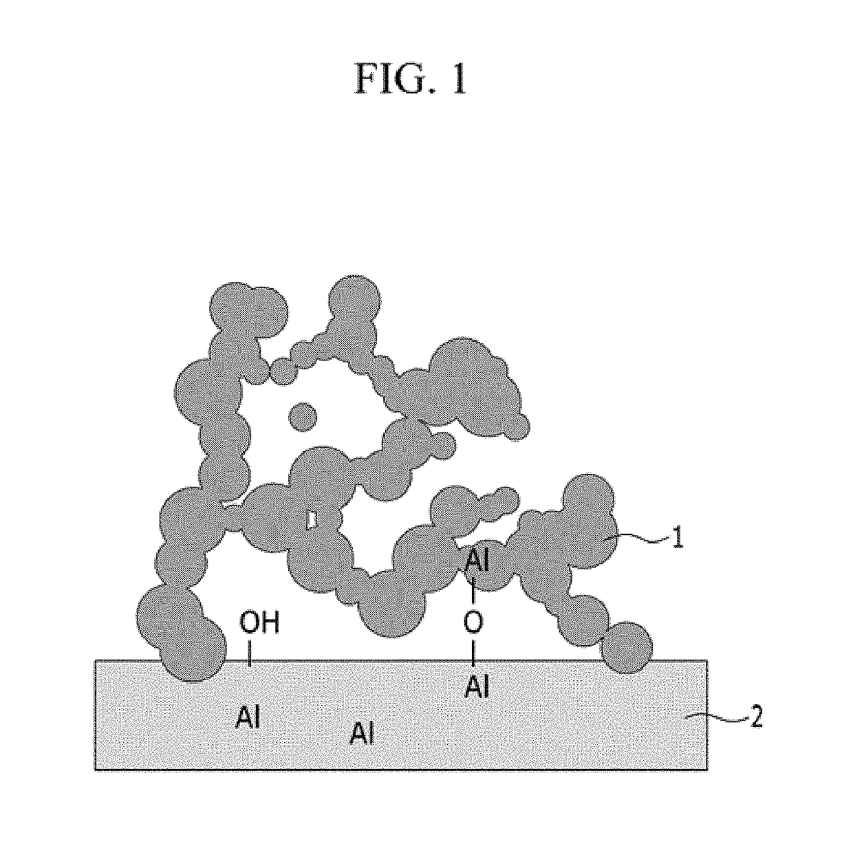
[0105]Alumina sol was prepared by stiffing a thermal insulation coating composition in which aluminum alkoxide (aluminum isopropoxide), ethanol, water and hydrochloric acid were mixed at a weight ratio shown in the following Table 1 below, followed by stirring at a temperature of 50° C. for 30 minutes. The alumina sol was coated on an aluminum alloy (ADC12) substrate, and left at a temperature of 70° C. for about 30 minutes, followed by gelation, thereby preparing an alumina wet gel.
[0106]An excessive amount of isopropyl alcohol (IPA) was added to the alumina wet gel so as to substitute solvents in the alumina wet gel with isopropyl alcohol, and a propoxytrimethylsilane / isopropyl alcohol (IPA) solution having a concentration of 0.1 wt % was added at a temperature of 30° C. for 60 minutes.
[0107]Then, the alumina wet gel was thermally treated at a temperature of 80° C. for 60 minutes to remove solvents such as ethanol, water, and ...
experimental example
Measurement of Physical Properties of Porous Thermal Insulation Coating Layers Obtained by Examples and Comparative Example
[0109]Physical properties of the porous thermal insulation coating layers obtained by Examples and Comparative Example were measured as follows, and results thereof were shown in the following Table 2.
[0110]1. Thermal Conductivity (W / mK)
[0111]With respect to the porous thermal insulation coating layers of Examples and Comparative Example, thermal conductivity was measured by thermal diffusion measurement method using a laser flash method at normal temperature and pressure according to ASTM E1461.
[0112]2. Volumetric Heat Capacity (KJ / m3K)
[0113]With respect to the porous thermal insulation coating layers of Examples and Comparative Example, heat capacity was confirmed by measuring specific heat using sapphire as a reference by differential scanning calorimetry (DSC) at room temperature according to ASTM E1269.
[0114]3. Porosity (%)
[0115]Porosity was measured on sur...
PUM
| Property | Measurement | Unit |
|---|---|---|
| Temperature | aaaaa | aaaaa |
| Temperature | aaaaa | aaaaa |
| Temperature | aaaaa | aaaaa |
Abstract
Description
Claims
Application Information
 - R&D Engineer
- R&D Manager
- IP Professional
- Industry Leading Data Capabilities
- Powerful AI technology
- Patent DNA Extraction
Browse by: Latest US Patents, China's latest patents, Technical Efficacy Thesaurus, Application Domain, Technology Topic, Popular Technical Reports.
© 2024 PatSnap. All rights reserved.Legal|Privacy policy|Modern Slavery Act Transparency Statement|Sitemap|About US| Contact US: help@patsnap.com