

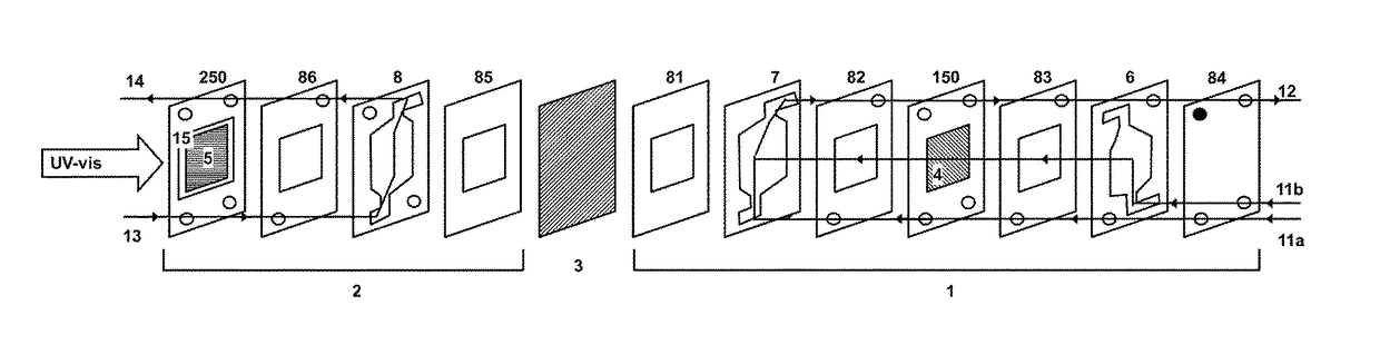
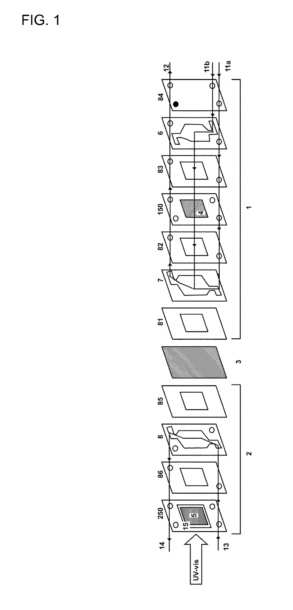
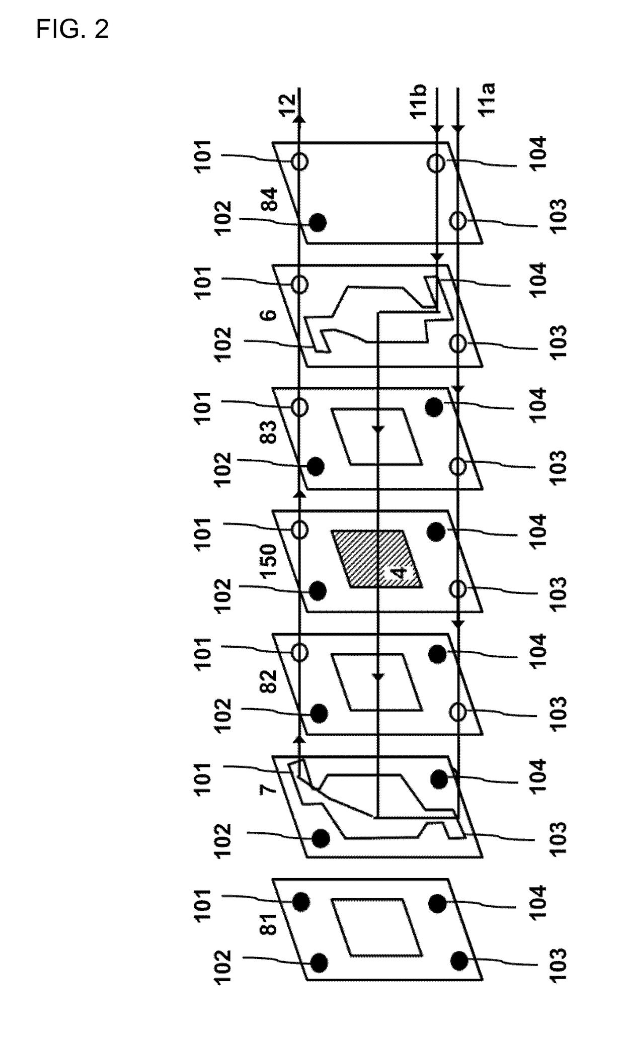
Filter-press photoelectrochemical water oxidation and co2 reduction cell
a photoelectrochemical and water oxidation technology, applied in the direction of energy input, metal/metal-oxide/metal-hydroxide catalyst, physical/chemical process catalyst, etc., can solve the problems of limited electrode stability in these conditions, low electrolytic conductivity, and use of cosub>2 /sub, etc., to maximize co2 selective conversion, reduce external energy supply, and high faradaic efficiency
- Summary
- Abstract
- Description
- Claims
- Application Information
AI Technical Summary
Benefits of technology
Problems solved by technology
Method used
Image

Examples
example 1
Electroreduction of CO2
[0125]To determine the working range of our photoelectrochemical system is necessary to characterize the electrochemical process under dark conditions, so that a similar cell without modification to accommodate the photoanode was used, working with a conventional anode and the cathode to be implemented in the photoelectrochemical cell. The working range of the photoelectrochemical process is one in which the electrochemical process under dark conditions does not occur.
[0126]Materials and Working Conditions:[0127]Anode: DSA (dimensionally stable anode) commercial—Ta2O5—IrO2 (area=10 cm2)[0128]Anolite: 0.5M NaOH or 0.5M KOH (10 mL min−1)[0129]Cathode: porous electrode, Sn supported on C-Toray (area =10 cm2)[0130]Catholite: 0.5M NaHCO3 or 0.5M NaHCO3 (10 mL / min)[0131]Gas: pure CO2(10 mL min−1).[0132]Protonic exchange membrane: Nafion 117,
[0133]In FIG. 10 is shown the cathode polarization as a function of absolute value of applied voltage. Cathode polarization is...
example 2
Carbon Dioxide Photoelectroreduction.
[0140]Materials and Working Conditions:[0141]Photoanode: TiO2 nanorods deposited on glass substrate coated with FTO (area=10 cm2)[0142]Anolite: 0.5M NaOH (10 mL min−1)[0143]Cathode: porous electrode, Sn supported on C-Toray (area =10 cm2)[0144]Catholite: 0.5M NaHCO3 (10 mL min−1)[0145]Gas: pure CO2 (10 mL min−1).[0146]Protonic exchange membrane: Nafion 117,[0147]Radiation flux: 100 mW cm−2
[0148]FIG. 14 shows the applied cell voltage (a), the individual anode potential (b), and individual cathode potential (c), of example 2 as a function of time. Applied voltage is stepped from 0.4 to 2.4 V at intervals of 0.2 V every 5 minutes.
[0149]As can be observed, contrary to what occurs in the process under dark conditions, cathode polarizes at applied cell voltages (|E|cell) lower than 1.8 V When the cell voltage increases, then photoanode polarization increases. Neverheless, contrary to what it is observed in the process under dark conditions, wherein in...
example 3
Photoelectroreduction of CO2 with Different photoanode / cathode Area Ratio.
[0151]The photoelectrochemical cell was adapted to accommodate different size cathodes (10, 5, 2, and 1 cm2) maintaining fixed the photoanode size (10 cm2).
[0152]Materials and Working Conditions:[0153]Photoanode: TiO2 nanorods deposited on glass substrate coated with FTO (area=10 cm2)[0154]Anolite: 0.5M NaOH (10 mL / min)[0155]Cathode: porous electrode, Sn supported on C-Toray (area =10, 5, 2 and 1 cm2)[0156]Catholite: 0.5M NaHCO3 (10 mL min−1)[0157]Gas: CO2 puro (10 mL min−1).[0158]Protonic exchange membrane: Nafion 117,[0159]Radiation flux: 100 mW cm−2, 200 mW cm−2, 500 mW cm−2 and 1000 mW cm−2.
[0160]FIG. 15 shows the evolution of the individual cathode (filled symbols) and anode (empty symbols) potentials (FIG. 15A) and the evolution of the photogenerated current intensity (FIG. 15B) as a function of absolute value of applied voltage (|E|cell) at different radiation fluxes: 100 mW cm−2 (squares), 200 mW cm−2 ...
PUM
| Property | Measurement | Unit |
|---|---|---|
| conductive | aaaaa | aaaaa |
| photocatalytic anodic | aaaaa | aaaaa |
| conductor | aaaaa | aaaaa |
Abstract
Description
Claims
Application Information