Motor drive device for controlling valve timing of internal combustion engine

a technology of internal combustion engine and drive device, which is applied in the direction of machines/engines, electronic commutators, stopping arrangements, etc., can solve the problems of affecting the operation of the motor from the stopped state, and achieve the effect of reducing increasing the drive torque, and restricting the vibration of the motor

Inactive Publication Date: 2018-03-08
DENSO CORP
View PDF0 Cites 2 Cited by
  • Summary
  • Abstract
  • Description
  • Claims
  • Application Information

AI Technical Summary

Benefits of technology

[0005]An object of the present disclosure is to provide a motor drive device for valve timing control of an internal combustion engine, which is capable of preventing a motor from becoming uncontrollable and reducing vibration of the motor.
[0006]According to an aspect of the present disclosure, a motor drive device for controlling valve timing of an internal combustion engine includes: a motor drive unit and a determination unit. The motor drive unit controls a phase of a camshaft to drive a motor for controlling opening and closing operation of a valve. The determination unit determines whether a timing is to start up the motor or to normally drive the motor. The motor drive unit drives the motor with an advance angle when it is determined that the timing is to normally drive the motor by the determination unit, and the motor drive unit normally drives the motor without the advance angle when it is determined that the timing is to start up the motor. Specifically, the determination unit determines whether cranking at the time of starting the engine is immediately after engine startup or not, and performs the normal control immediately after the start of the engine to increase the drive torque without performing the advance angle control. As a result, the drive torque does not fall below the detent torque, and the motor no longer repeats forward / reverse rotation, such that vibration of the motor can be restricted.

Problems solved by technology

When the motor comes to the vibration state, a control device may erroneously determine that the motor is in a regenerative state at the time of reverse rotation of the motor.
In this case, if it transits to a regenerative control, the control may be disabled from a stopped state of the motor.

Method used


Image

  • Motor drive device for controlling valve timing of internal combustion engine
  • Motor drive device for controlling valve timing of internal combustion engine
  • Motor drive device for controlling valve timing of internal combustion engine

Examples


first embodiment

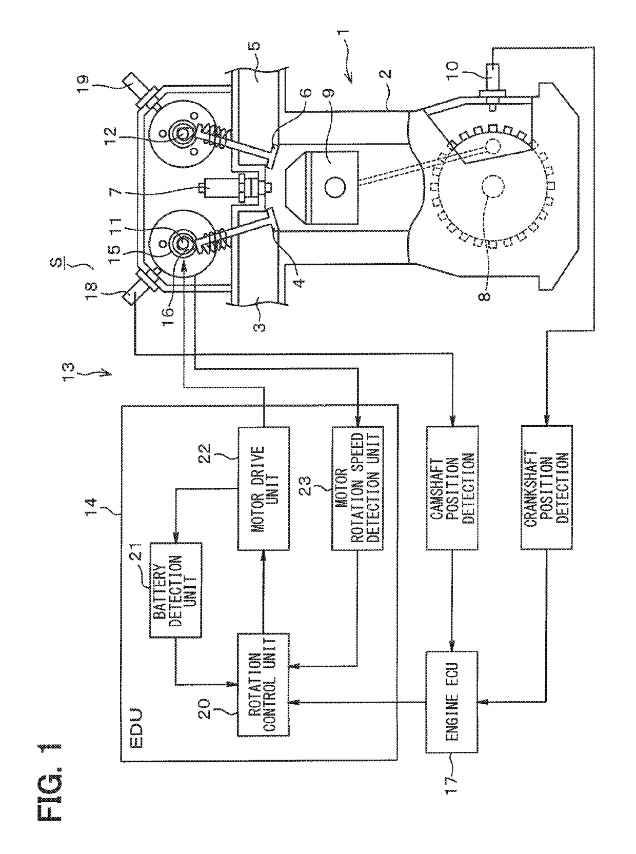
[0031]FIGS. 1 to 11 schematically show a first embodiment. FIG. 1 shows a configuration of an electric variable cam timing (VCT) system S. A control system in which a driving source of a VCT system is operated by an electric motor is referred to as an electric VCT system S. The electric VCT system S is a system for optimizing the opening and closing timing of a valve, and can perform an improvement in a fuel consumption caused by a reduction in an exhaust emission and a reduction in a pumping loss, and an improvement in an engine output caused by an improvement in intake and exhaust efficiency.

[0032]An engine block 2, an intake path 3, an intake valve 4 that is disposed in the intake path 3, an exhaust path 5, an exhaust valve 6 that is disposed in the exhaust path 5, an ignition spark plug 7, a crankshaft 8, a piston 9, and so on are installed in an engine body 1 as an internal combustion engine. A crank angle sensor 10 is installed outside the crankshaft 8, and the crank angle sen...

second embodiment

[0081]FIGS. 12 to 15 illustrate additional illustrative views of a second embodiment. In the second embodiment, reset is continued until the battery voltage VB exceeds the torque threshold voltage so that the torque becomes sufficient.

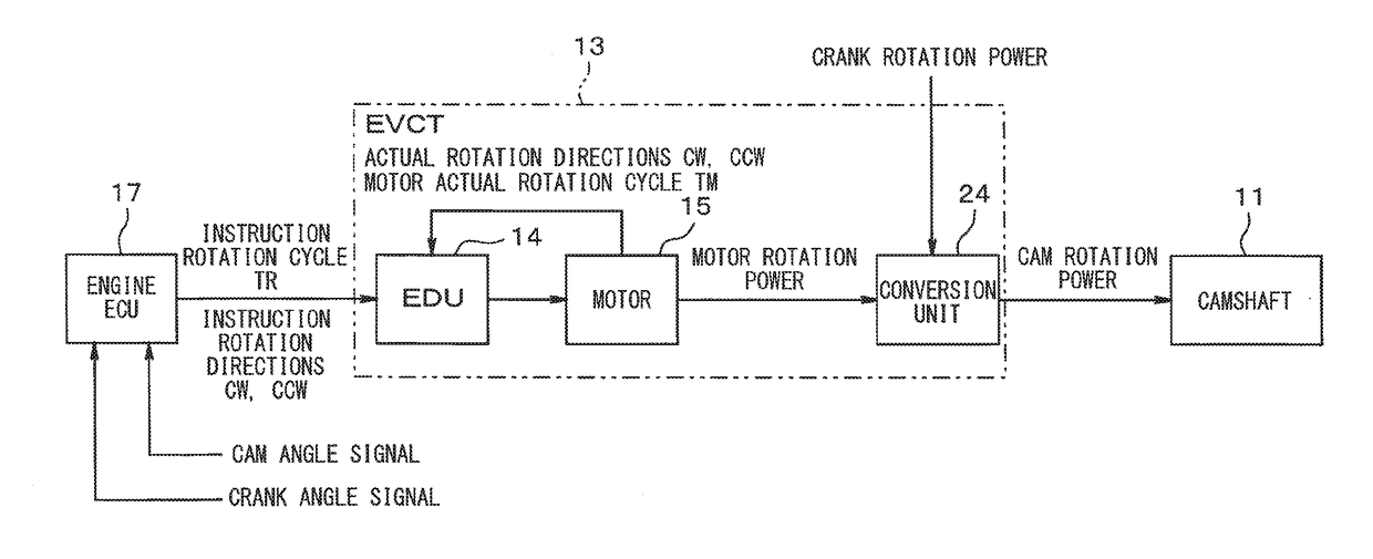
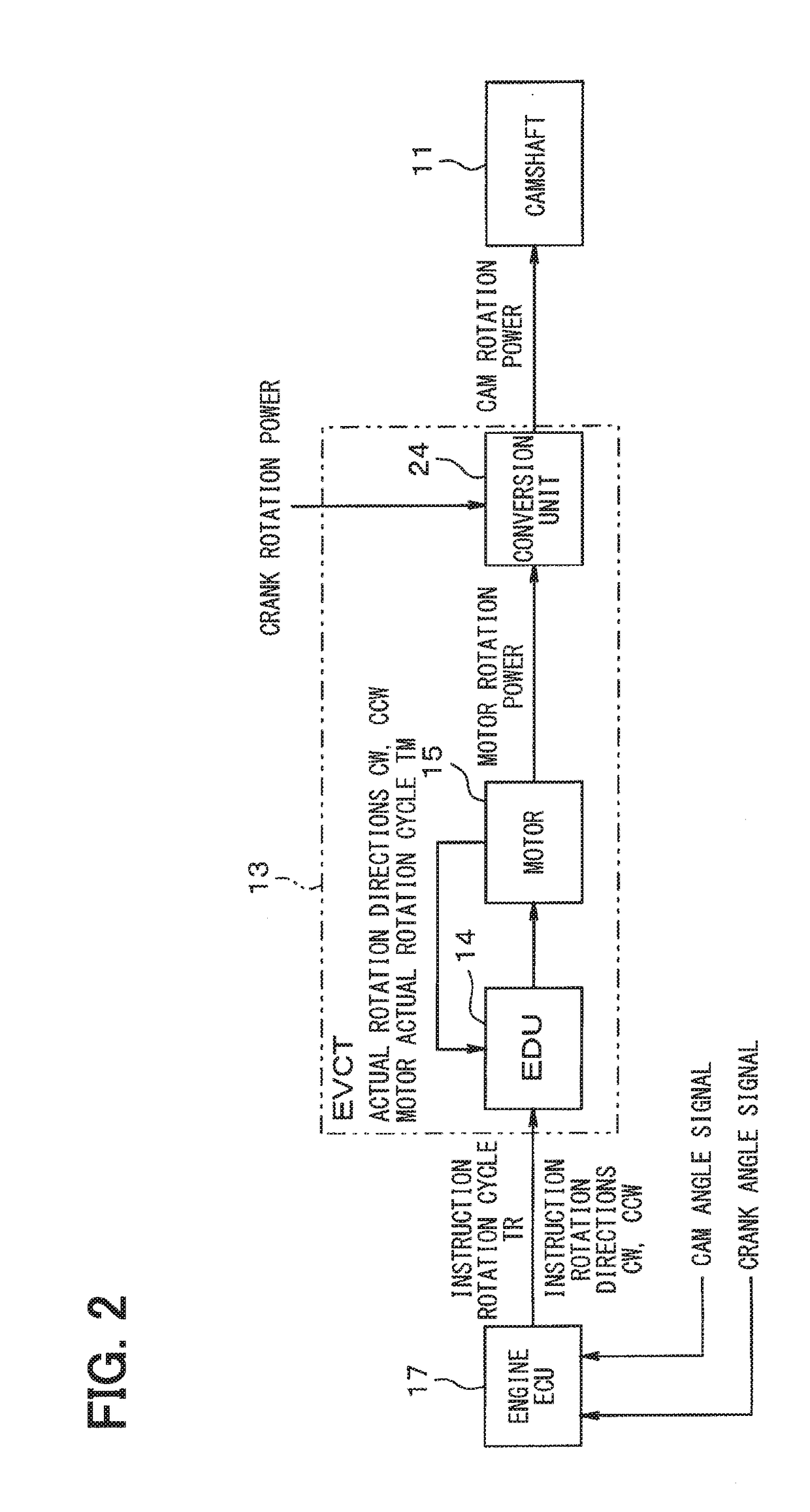
[0082]FIG. 12 shows a configuration diagram of an electric VCT system S2 which is substituted for FIG. 1. The electric VCT system S2 includes a valve timing control motor drive device 113. The valve timing control motor drive device 113 includes an EDU 114, a motor 15 that operates with the use of a battery electric power, and a conversion unit 24 that transmits a cam rotation power to a camshaft 11 with the use of a rotation power of the motor 15 and a rotation power of a crankshaft 8. The valve timing control motor drive device 113 transmits a power generated by the conversion unit 24 to the camshaft 11 under the control of an engine ECU 17 so as to change a cam phase.

[0083]The EDU 114 is configured by combining circuits of a microcomputer such as an...

third embodiment

[0097]FIG. 16 shows an illustrative view according to a third embodiment. FIG. 16 schematically shows the contents of a reset continuation determination process in place of FIG. 15. As shown in FIG. 16, when it is determined that a vibration flag is “1” in T1, a rotation control unit 120 may determine whether a predetermined time has elapsed, or not, with the use of, for example, a timer in T2a, and may determine that the reset is continued, or not, in T3.

[0098]In other words, if the predetermined time has not elapsed, a drive control unit 120b of the rotation control unit 120 stops driving a motor 15 by a motor drive unit 22 until it is determined that the predetermined time has elapsed. When the predetermined time has elapsed, the drive control unit 120b of the rotation control unit 120 starts to drive the motor 15 by the motor drive unit 22. Therefore, if it can be guaranteed that the battery voltage VB has increased to such an extent that the battery voltage VB does not oscillat...


PUM


Abstract

A motor drive device for valve timing control of an internal combustion engine includes: a motor drive unit that controls a phase of a camshaft to drive a motor for controlling opening and closing operation of a valve; and a determination unit that determines whether a timing is to start up the motor or to normally drive the motor. The motor drive unit drives the motor with an advance angle when it is determined that the timing is to normally drive the motor by the determination unit, and the motor drive unit normally drives the motor without the advance angle when it is determined that the timing is to start up the motor.

Description

CROSS REFERENCE TO RELATED APPLICATION[0001]This application is based on Japanese Patent Application No. 2015-114798 filed on Jun. 5, 2015, and Japanese Patent Application No. 2015-231735 filed on Nov. 27, 2015, the disclosures of which are incorporated herein by reference.TECHNICAL FIELD[0002]The present disclosure relates to a motor drive device for controlling a valve timing of an internal combustion engine.BACKGROUND ART[0003]In order to obtain an optimum torque and an optimum output of an engine, an electric variable cam timing (VCT) system grasps an operation state such as a rotation speed and an accelerator opening degree, and continuously controls a phase of a cam. In this manner, the electric variable cam timing system optimizes opening and closing timing of an intake valve for supplying an air to the engine and an exhaust valve for discharging an exhaust gas. In Patent Literature 1, in the case where the engine is stopped when the cam is in an advance angle state, a phase ...

Claims


Application Information

Patent Timeline
Patent Type & Authority Applications(United States)
IPC IPC(8): F01L1/356B60R16/023H02P6/08H02P6/15H02P6/24
CPCF01L1/356B60R16/0232H02P6/08H02P6/153H02P6/157H02P6/24H02P2205/05F01L1/344F01L2001/0537F01L2201/00F01L2250/02F01L2800/01F01L2810/03F01L2820/032F01L2820/041
Inventor KISHIMOTO, YOSHIFUMISATO, MASATAKE
Owner DENSO CORP
Why Eureka
Try Eureka