Printed transparent heaters using embedded micro-wires

a technology of embedded micro-wires and heaters, applied in the field of heaters, can solve the problems of non-uniform power density, display may not function properly, and response can be very slow, and achieve excellent heating characteristics and higher power capacity

Active Publication Date: 2018-03-08
EASTMAN KODAK CO
View PDF2 Cites 17 Cited by
  • Summary
  • Abstract
  • Description
  • Claims
  • Application Information

AI Technical Summary

Benefits of technology

[0017]This invention has the advantage that the heater is virtually transparent so that it can be applied over a display or some other surface without visibly obscuring the image content, while providing excellent heating characteristics.
[0018]It has the additional advantage that the transparent heater has a flat surface where the wires do not substantially protrude from the surface.
[0019]It has the further advantage that the micro-wires have a higher power capacity than conventional signal-carrying micro-wires.

Problems solved by technology

Below that, the response can be very slow, or the display may not function properly.
A common drawback of film heaters based on continuous conductive sheets is that they suffer from non-uniform power density due to the variation of film thickness at different location, and from voltage drop along the bus bars.
(For example, see U.S. Pat. No. 5,886,763 to Wolkowicz et al., entitled “LCD heater utilizing z-axis conductive adhesive to attach bus bars to ITO;” U.S. Pat. No. 5,247,374, to Terada, entitled “Liquid crystal display device with common heater between two cells;” and U.S. Pat. No. 5,523,873 to Bradford III et al., entitled “LCD heater with flex circuit buss bars.”) However, ITO films have a number of significant disadvantages including slow thermal response, higher materials cost and limited resources, and fragility due to their brittleness.
Moreover, the most common method to fabricate ITO films is vacuum deposition which is both expensive and time consuming.
However, each of these approaches has inherent limitations, and all continuous films are subject to non-uniform power density as ITO films.
1245-1248) also involves a costly and time-consuming photolithographic process.
In addition, such wires are formed on top of the substrate, creating an uneven surface which is not favorable for subsequent integration such as lamination onto displays.
Although this approach avoids the protrusion of wires, the wire size (400 μm) is too large for the wires to be invisible to a human observer.
Furthermore, the fabrication process is not suitable for large scale manufacturing.
While such configurations are well-suited for signal transmission as required for touch sensors, the size of the micro-wires is intrinsically limited by the conventional fabrication methods, and therefore they are unsuitable to transmit sufficient power for heater applications.

Method used


Image

  • Printed transparent heaters using embedded micro-wires
  • Printed transparent heaters using embedded micro-wires
  • Printed transparent heaters using embedded micro-wires

Examples


example 1

Transparent and Flexible Heater Using PET Substrate

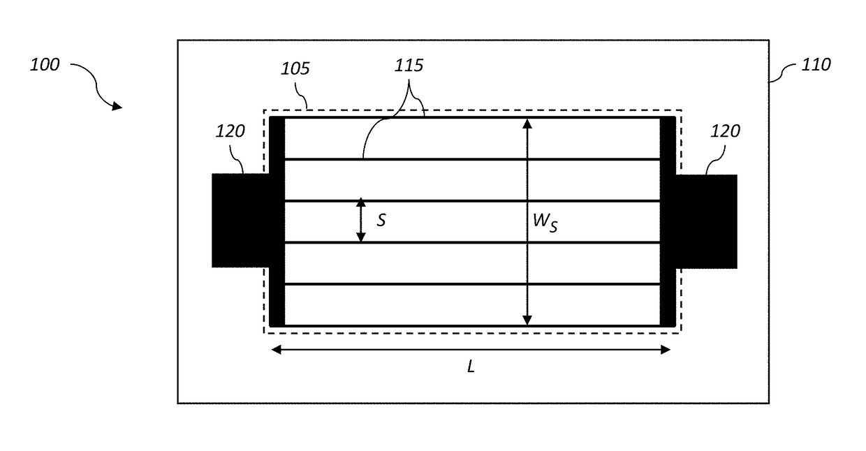
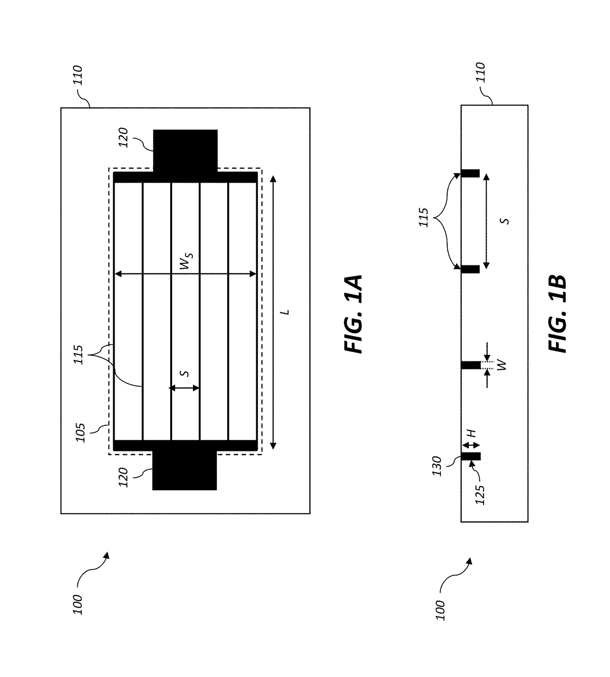
[0095]An exemplary transparent heater 100 was fabricated on a PET substrate 110 using the micro-wire pattern shown in FIG. 14. This exemplary heater was designed to provide a useful temperature range between room temperature and 120° C. The fabricated transparent heater 100 was sandwiched between two PDMS sheets (having a 2 mm thickness) during testing. The micro-wires 115 were configured to have a width of W=5 μm wide, a thickness of H=14 μm, and a total length of L=2.4 m, and were arranged in zig-zag shape (as in FIG. 9B). Four parallel micro-wires 115 were grouped together with an inter-wire spacing of S=250 μm.

[0096]Various measurement results are summarized in the first column of Table 2. The measured resistance is 476Ω at room temperature, corresponding to a single wire resistance of 1904Ω. The normalized resistance per unit length for one wire was calculated to be R / L=793 Ω / m. This is about 11% higher than the theoretical val...

example 2

High Temperature Transparent Heater Using Glass Substrate

[0098]Another exemplary transparent heater 100 was fabricated on a glass substrate using the micro-wire pattern shown in FIG. 14. This exemplary heater configuration was designed to provide a larger temperature range useful temperature range from room temperature up to 200° C. The performance was measured using a similar procedure and the results are summarized in the second column of Table 2. FIG. 15B shows a graph 310 plotting the resulting temperature as a function of the voltage and current supplied to the transparent heater. At the maximum voltage that was tested (60 V) a surface temperature of 205° C. was obtained.

TABLE 2Example 1Example 2SubstratePETGlassConductorSilver inkSilver inkWidth, W (μm)55Thickness, H (μm)1418Aspect ratio (H / W)2.83.6Length, L (m)2.42.05Resistance, R (Ω)1904 (1 wire)1252 (1 wire)  476 (4 wires)  313 (4 wires)Resistance / length (Ω / m)793611Max current tested (A)0.0210.032Max current density tested ...


PUM


Abstract

A transparent heater includes a plurality of high aspect ratio micro-wires. A plurality of channels is formed into the surface of a transparent substrate within an active heater region. The channels have a width of between 4 microns and 9 microns to insure that they are invisible to the naked eye, and a depth that is at least 1.5 times the width. Spacing between the channels is preferably at least 100 μm. Micro-wires are formed by at least partially filling the channels with a conductive material. Power source connections are provided to connect to an electrical power source to supply a current through the plurality of micro-wires. An average optical transmittance of the transparent heater within the active heater region is greater than 50 percent.

Description

FIELD OF THE INVENTION[0001]This invention pertains to the field of heaters for transparent substrates, and more particularly to heaters using micro-wires that are invisible to a human observer.BACKGROUND OF THE INVENTION[0002]Many industries utilize film heaters, such as automotive, avionics, displays, art conservation, and similar fields, to ensure stable operation of electronic devices under harsh environmental conditions. For example, many LCD displays are rated to degree 0° C. (32° F.) as a minimum operating temperature. Below that, the response can be very slow, or the display may not function properly. Film heaters can be used to maintain the display at an acceptable operating temperature. Optical transparency of the film heater in the visible light range is a requirement in applications such as automobile windshields, electronic displays, and helmet facial shields, or can provide substantial benefits for applications such as microfluidics polymerase chain reactions (PCR) to ...

Claims


Application Information

Patent Timeline
Patent Type & Authority Applications(United States)
IPC IPC(8): H05B3/84H05K1/02H05K1/03H05K3/00
CPCH05B3/84H05K1/0212H05K1/0274H05K1/028H05K1/0306H05B2203/017H05K3/0017H05K2201/09036H05B2214/04H05B2203/004H05B2203/003H05K1/0313H05B3/86H05B2203/013H05K1/167H05K3/1258H05K2201/0108
Inventor WEI, HAOYAN
Owner EASTMAN KODAK CO
Why Eureka
Try Eureka