Process For Converting Carbonaceous Material Into Low Tar Synthetic Gas

a carbonaceous material and synthetic gas technology, applied in the direction of combustible gas catalytic treatment, combustible gas purification/modification, combustible gas production, etc., can solve the problems of large tar production, inability to scale up to economically attractive scales, and many gasification processes known in the ar

Inactive Publication Date: 2018-03-29
EXPANDER ENERGY
View PDF0 Cites 13 Cited by
  • Summary
  • Abstract
  • Description
  • Claims
  • Application Information

AI Technical Summary

Benefits of technology

[0032]wherein the reduction zone is provided with an inwardly and downwardly angled perforated floor and a deflector located in the center of the floor, wherein the floor and deflector are configured to form a bed of pyrolysis residue having a uniform depth.

Problems solved by technology

Many of the gasification processes known in the art have failed due to insufficient attention to low tar production or efficient tar destructions.
Existing downdraft gasifiers require very high quality wood fuels or biomass, such as ash free wood blocks or high quality wood chips, and cannot be scaled up to economically attractive scales without severely increased tar production.
Multi-stage downdraft gasifiers which comprise separate zones for fuel pyrolysis, partial oxidation, and reduction of bed gas, have also been developed, however such gasifiers known in the art also result in substantial amount of tar production, significant tar levels retained in the syngas and the ash also containing very high levels of unconverted carbon content
This gasifier is structurally complicated, and is known for its poor controllability and flexibility of performance, and lacks any reduction zone to reduce tar content in the product gases.
The devices / systems of CZ 295,171 and WO 2015 / 090251, result in considerable amount of tar in the product gases, which in turn clogs the cleaning devices used to clean the product gases.
Further the WO 2015 / 090251 has no means to effectively manage the reduction reactions and failed to produce consistent flow and quality of syngas

Method used


Image

  • Process For Converting Carbonaceous Material Into Low Tar Synthetic Gas
  • Process For Converting Carbonaceous Material Into Low Tar Synthetic Gas
  • Process For Converting Carbonaceous Material Into Low Tar Synthetic Gas

Examples


Embodiment Construction

Definitions

[0037]As used herein, the term “about” refers to a + / −10% variation from the nominal value. It is to be understood that such a variation is always included in a given value provided herein, whether or not it is specifically referred to.

[0038]Unless defined otherwise, all technical and scientific terms used herein have the same meaning as commonly understood by one of ordinary skill in the art to which this invention belongs.

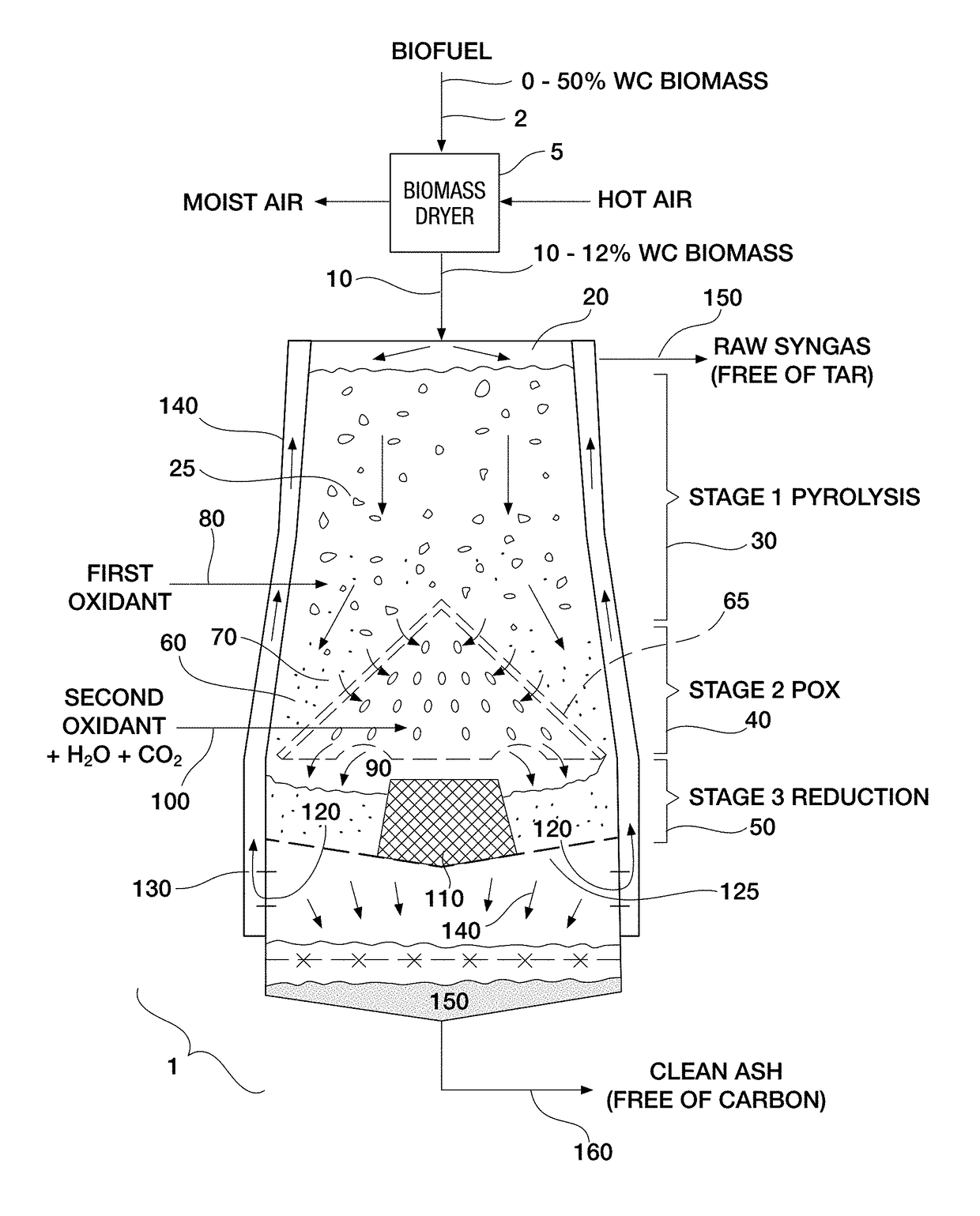
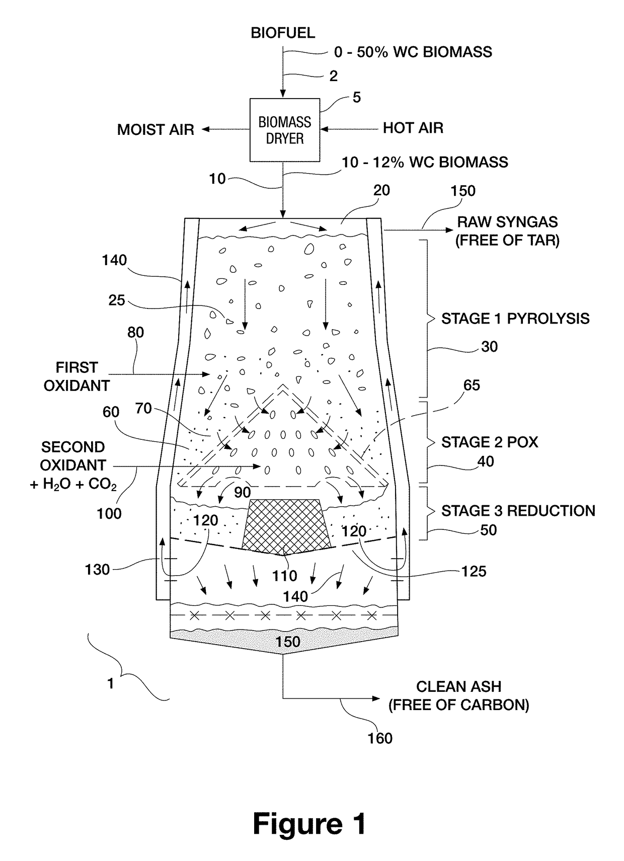
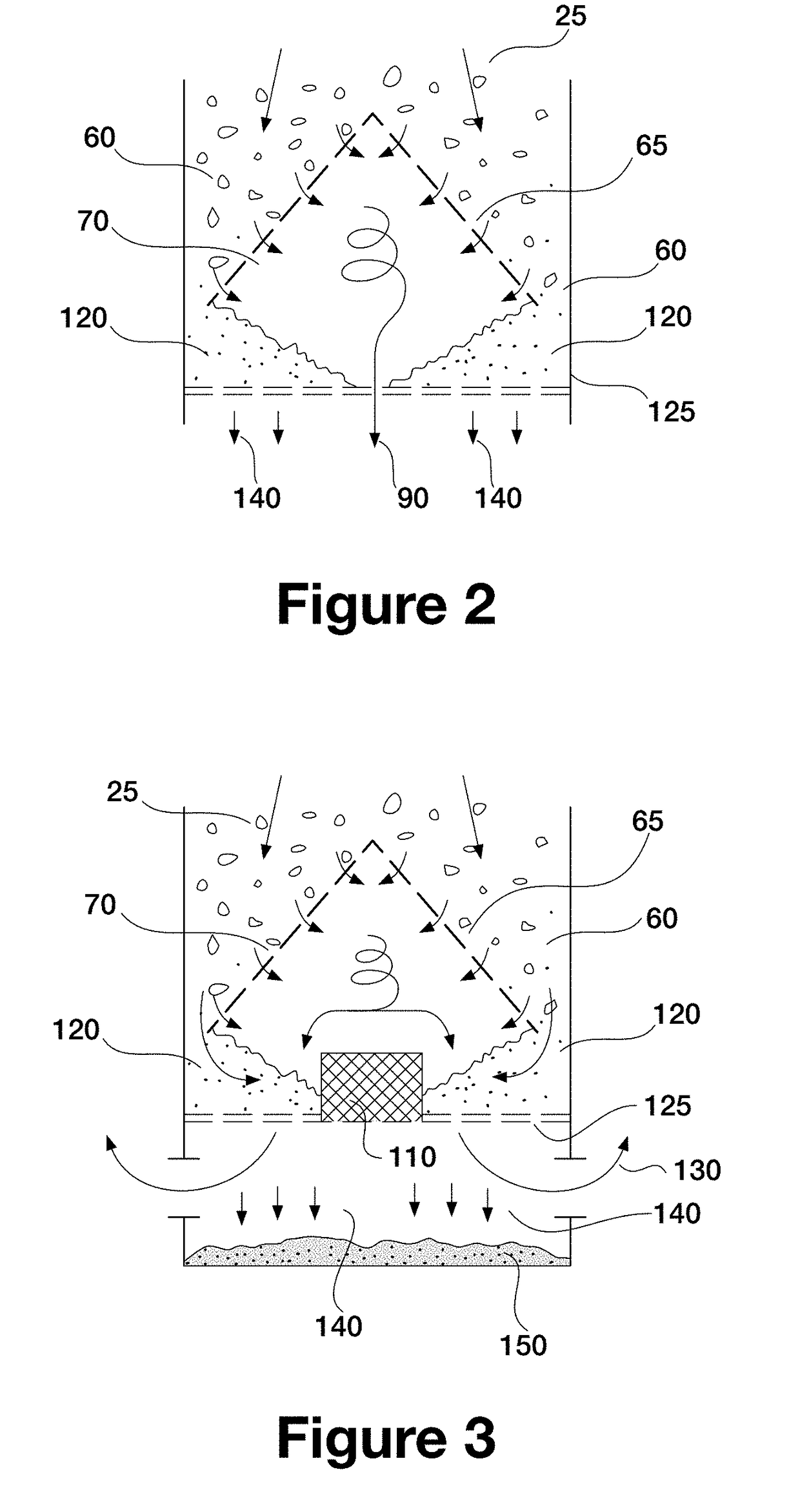
[0039]In one aspect of the present invention, there is provided a continuous multi-stage vertically sequenced gasification process for conversion of solid carbonaceous fuel material into clean (low tar) syngas in a gasifier comprising a pyrolysis zone, a partial oxidation zone located vertically downstream of the pyrolysis zone, and a reduction zone located vertically downstream of the partial oxidation zone and comprising an inwardly and downwardly angled perforated floor / base and a deflector located in the center of the floor. The angle of the floor ...


PUM

PropertyMeasurementUnit
temperatureaaaaaaaaaa
atmospheric pressureaaaaaaaaaa

Abstract

A continuous multi-stage vertically sequenced gasification process for conversion of solid carbonaceous fuel material into clean (low tar) syngas. The process involves forming a pyrolysis residue bed having a uniform depth and width to pass raw syngas there through for an endothermic reaction, while controlling the reduction zone pressure drop, resident time and syngas flow space velocity during the endothermic reaction to form substantially tar free syngas, to reduce carbon content in the pyrolysis residue, and to reduce the temperature of raw syngas as compared to the temperature of the partial oxidation zone.

Description

CROSS-REFERENCE TO RELATED APPLICATIONS[0001]This application claims benefit of U.S. Provisional Patent Application No. 62 / 401,711 filed Sep. 29, 2016, which is hereby incorporated by reference as part of the present disclosure.FIELD OF THE INVENTION[0002]The present invention pertains to the field of gasification of carbonaceous feedstock / fuel, and in particular to a process and system for conversion of carbonaceous fuel materials into clean high quality syngas substantially devoid of tars and for the production of clean ash substantially devoid of carbon content.BACKGROUND[0003]Gasification can convert carbon-containing materials to useful chemical products. These chemical products typically involve synthesis gas (syngas), which can be further combusted to produce electricity, or chemically reacted to produce oxygenates or hydrocarbons in catalytic systems.[0004]Several types of gasification and pyrolysis methods and apparatuses have been developed to achieve efficient conversion ...

Claims


Application Information

Patent Timeline
Patent Type & Authority Applications(United States)
IPC IPC(8): C10J3/66C10J3/82C10K3/02C10B3/00C10B49/04C10B53/02C10B57/16C10B57/06
CPCC10J3/66C10J2300/1846C10K3/026C10B3/00C10B49/04C10B53/02C10B57/16C10B57/06C10J2300/0946C10J2300/092C10J2300/0923C10J2300/0943C10J2300/093C10J2300/0959C10J3/82C10J3/02C10J3/06C10J3/14C10J3/16C10J3/20C10J3/24C10J3/26C10J3/40C10J3/721C10J3/74C10J3/84C10J2300/0906C10J2300/0913C10J2300/0956C10J2300/0969C10J2300/1246C10J2300/1884Y02E50/30Y02E50/10C10J3/36
Inventor KRESNYAK, STEVEZAHORIK, PAVEL
Owner EXPANDER ENERGY
Why Eureka
Try Eureka