Flight Planning for Unmanned Aerial Tower Inspection with Long Baseline Positioning

a technology for aerial towers and flight planning, applied in the direction of position/course control, measurement devices, instruments in three dimensions, etc., can solve the problems of low signal-to-noise ratio, difficult to get into rough terrain, and expensive mobilization of bucket trucks, etc., and achieve accurate calculation

Active Publication Date: 2018-04-05
VAN CRUYNINGEN IZAK
View PDF14 Cites 39 Cited by
  • Summary
  • Abstract
  • Description
  • Claims
  • Application Information

AI Technical Summary

Benefits of technology

[0020]FIG. 1 is a perspective view of transmission tower 10, phase conductors 12, insulators 14, and shield wires 15. They are to be inspected by unmanned aerial vehicle UAV 20 with embedded processor and memory 22, radio 24, location rover 26, and camera 28. Continuously operating reference station 16 has GNSS antenna 17, GNSS receiver 19, and radio 18. The relative location between UAV 20 and reference station 16 can be accurately calculated using location corrections sent by radio 18 to radio 24. Camera 28 on UAV 20 is first used to

Problems solved by technology

For example, problems in power transmission lines include:insulator contamination from salt, pollution, avian waste, or cumulative partial discharge;tower corrosion or avian nesting;lightning strike damage on shield wires or surge arrestors; andright-of-way incursion by vegetation or man-made structures.
Bucket trucks are expensive to mobilize and difficult to get into rough terrain.
To locate defects from the ground requires instruments with narrow fields of view and very high gain, yet they still tend to have low signal to noise ratios.
Similarly, an optical camera with a high power zoom lens has a very narrow field of view to focus on finding a defect, but it requires high ISO settings and thus produces noisier images.
Low signal levels usually require averaging over a number of readings to reliably detect defects, thereby further slowing down the inspection.
It is even more difficult to provide full inspection coverage in a rapidly moving manned aerial platform.
Instruments with a narrow field of view potentially miss many defects, while instruments with a wide field of view make it difficult to accurately locate the defect.
However, flying a UAV manually in an inspection poses a number of problems:Learning to fly by remote control is a significant challenge for most operators.
It requires

Method used


Image

  • Flight Planning for Unmanned Aerial Tower Inspection with Long Baseline Positioning
  • Flight Planning for Unmanned Aerial Tower Inspection with Long Baseline Positioning
  • Flight Planning for Unmanned Aerial Tower Inspection with Long Baseline Positioning

Examples


Embodiment Construction

[0035]This section describes several embodiments of the tower inspection system with reference to FIGS. 1-4.

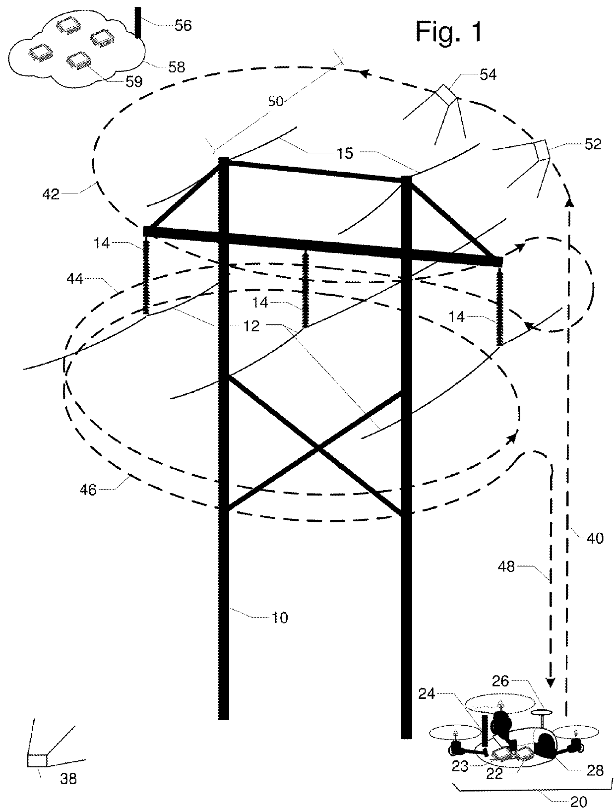
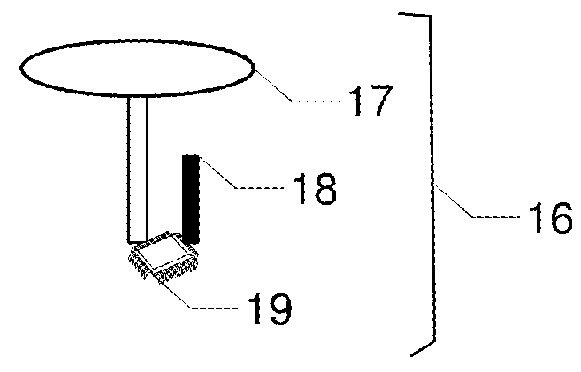
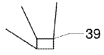
[0036]FIG. 1 is a perspective view of a transmission line H-tower 10 commonly used in single circuit transmission lines. Tower 10 supports insulators 14, which in turn support phase conductors 12. Tower 10 also supports shield wires 15 that reduce the impact of lightning strikes. A continuously operating reference station 16 with GNSS antenna 17, radio 18, and GNSS receiver 19 is located at a known fixed position remote from tower 10. An unmanned aerial vehicle (UAV) 20 has embedded processor and memory 22, inertial measurement unit (IMU) 23, radio 24, location rover 26, and camera 28. Orientation images 38 and 39 are taken from several vantage points. The inspection resolution and safety requirements determine standoff distance 50. Flight path with segments for ascent 40; loops 42, 44, and 46; and descent 48 maintains standoff distance 50 while providing complete inspection c...


PUM


Abstract

FIG. 1 is a perspective view of transmission tower 10, phase conductors 12, insulators 14, and shield wires 15. They are to be inspected by unmanned aerial vehicle UAV 20 with embedded processor and memory 22, radio 24, location rover 26, and camera 28. Continuously operating reference station 16 has GNSS antenna 17, GNSS receiver 19, and radio 18. The relative location between UAV 20 and reference station 16 can be accurately calculated using location corrections sent by radio 18 to radio 24. Camera 28 on UAV 20 is first used to capture two or more orientation images 38 and 39 of tower 10; lines 12 and 15; and insulators 14 from different vantage points. Terrestrial or close-range photogrammetry techniques are used create a three dimensional model of tower 10; lines 12 and 15; and insulators 14. Based on inspection resolution and safety objectives, a standoff distance 50 is determined. Then a flight path with segments for ascent 40, one or more loops 42, 44, 46, and a descent 48 is designed to ensure full inspection coverage via inspection images like 52 and 54.

Description

CROSS-REFERENCE TO RELATED APPLICATIONS[0001]This application claims the benefit of provisional patent application Ser. No. 62 / 134,920 filed 2015 Mar. 18 by the present inventor, which is incorporated by reference. This application is related to application PCT / US2106 / 020297, which is incorporated by reference.BACKGROUNDPrior Art[0002]Inspection, survey, or reconnaissance of towers and overhead lines aids in maintenance planning to prevent outages and deterioration. For example, problems in power transmission lines include:[0003]insulator contamination from salt, pollution, avian waste, or cumulative partial discharge;[0004]tower corrosion or avian nesting;[0005]lightning strike damage on shield wires or surge arrestors; and[0006]right-of-way incursion by vegetation or man-made structures.[0007]Ground-based inspection of towers, poles, utility corridors, and high voltage facilities such as substations is well known. For example, on high voltage transmission lines inspectors use a va...

Claims


Application Information

Patent Timeline
IPC IPC(8): G05D1/10G01S19/14G01S17/89
CPCG05D1/101G01S19/14G01S17/89G01S19/43G05D1/0094
Inventor VAN CRUYNINGEN, IZAK JAN
Owner VAN CRUYNINGEN IZAK
Why Eureka
Try Eureka