
Method for controlling crystal plane of polycrystalline metal and metal-carbon material composite including metal where crystal plane is controlled by using the same

a technology of metal-carbon composites and crystal planes, which is applied in the direction of after-treatment details, liquid/solution decomposition chemical coatings, and insulation conductors/cables, etc., can solve the problems of accelerating corrosion rate, electrical conductivity, heat conductivity, and negative effects on physical properties of materials, so as to achieve easy preparation of metal-carbon composites, easy to induce and suppress, and low cost

Inactive Publication Date: 2018-04-19
KOREA INST OF SCI & TECH
View PDF1 Cites 0 Cited by
  • Summary
  • Abstract
  • Description
  • Claims
  • Application Information

AI Technical Summary

Benefits of technology

The present disclosure describes a method for controlling the crystal plane of a polycrystalline metal and mass-producing a metal-carbon material composite. This method is simple, cost-effective, and can induce or suppress the growth of a specific crystal plane of the metal. The resulting composite has flexible and excellent electrical conductivity and mechanical properties. This composite can be easily produced and used in various fields such as wired / wireless communication, electrode material, and electromagnetic wave shielding material. The unique feature of this patent is the ability to mass-produce a single crystal-like metal at low costs through a continuous process using a polycrystalline metal.

Problems solved by technology

However, the crystal grain boundary in the polycrystal is considered as a defect in a crystal structure, and thus becomes a factor negatively affecting physical properties of a material, such as electrical conductivity, heat conductivity, decrease in strength, and acceleration of corrosion rate.
Therefore, in order to secure excellent physical properties, a form of single crystals is needed, but a method for growing single crystals is trickier than a method for growing polycrystals as described below, and has a problem in that the amount of single crystals produced is relatively small and preparation costs are high.
However, for the methods for preparing a single crystalline metal, the preparation costs thereof are high, and it is difficult to mass-produce the single crystalline metal.

Method used


Image

  • Method for controlling crystal plane of polycrystalline metal and metal-carbon material composite including metal where crystal plane is controlled by using the same
  • Method for controlling crystal plane of polycrystalline metal and metal-carbon material composite including metal where crystal plane is controlled by using the same
  • Method for controlling crystal plane of polycrystalline metal and metal-carbon material composite including metal where crystal plane is controlled by using the same

Examples


example 3

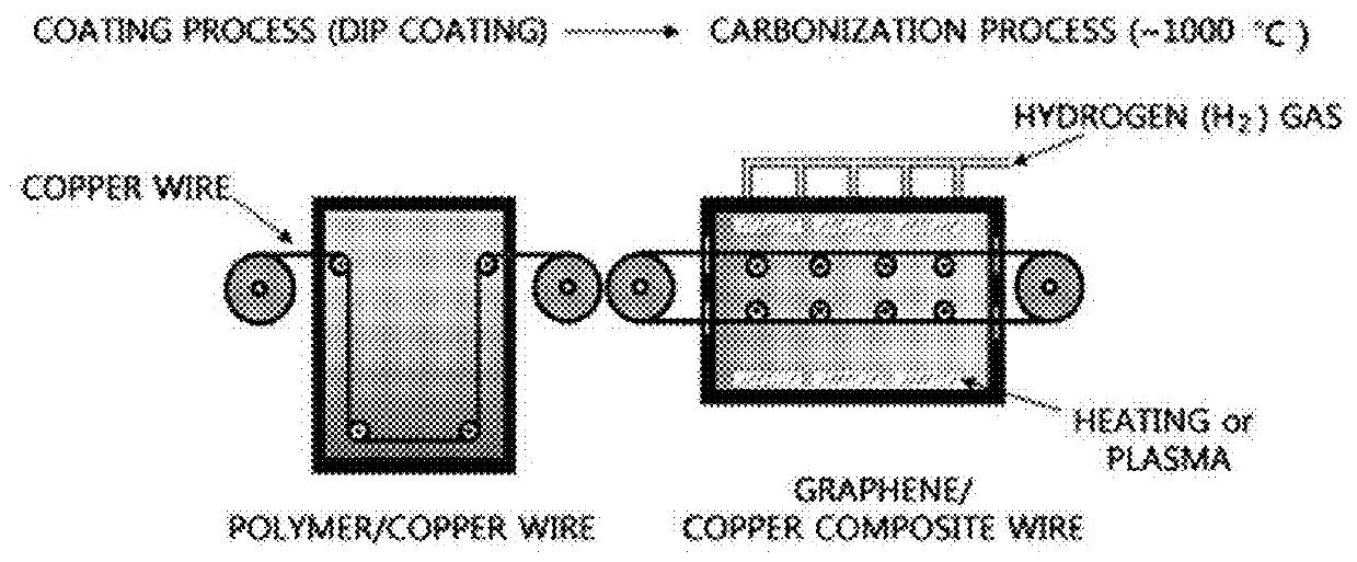
[0153]A graphene / copper composite wire was prepared through the same process, except for the concentration of the polymer solution, the carbonization process time, and gas flow rate in Example 2. The copper wire was coated by using a polymer solution in an amount of 3.0% based on the weight of the polar solvent. Subsequently, a carbonization treatment was performed for 90 minutes by increasing the temperature to 700° C. under a hydrogen:argon gas atmosphere at a flow rate of 5:100, 5:0, and 50:0 sccm.

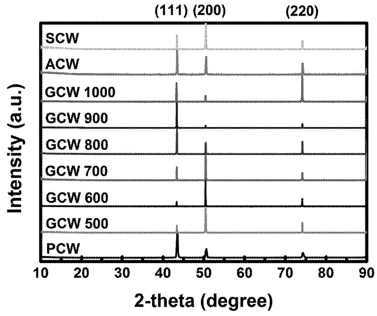
[0154]FIG. 11 is an XRD graph of a graphene / copper composite prepared according to the gas flow rate during the carbonization process in Example 3 of Experiment 1 of the present disclosure and coppers in the Comparative Examples. In FIG. 11, an incident angle (unit: degree) of X ray is marked on the X-axis, and the intensities (no unit) of a pure polycrystalline copper wire (PCW) in Comparative Example 1, a graphene / copper composite (hydrogen:argon flow rate (unit: sccm)) for each gas f...

example 4

[0162]A graphene / copper composite wire was prepared through the same process, except for the gas flow rate and pressure conditions during the carbonization process in Example 3. The gas flow rate during the carbonization process was fixed at 5 sccm, and a heat treatment was performed by changing the carbonization pressure into each of reduced pressure (70 mTorr) (LP) and atmospheric pressure (760 Torr) (AP).

[0163]FIG. 15 is an XRD graph of a graphene / copper composite prepared according to the carbonization process pressure in Example 4 of Experiment 1 of the present disclosure. In FIG. 15, an incident angle (unit: degree) of X ray is marked on the X-axis, and the intensities (no unit) of pure polycrystalline copper (PCW) in Comparative Example 1, a graphene / copper composite for each pressure (GCW pressure) of the carbonization process in Example 4, heat-treated pure polycrystalline copper (ACW) in Comparative Example 2, and pure single crystalline copper (SCW) in Comparative Example...

example 5

[0172]A graphene / copper composite wire was prepared through the same process, except for the concentration of the polymer solution, the carbonization process time, gas flow rate, and presence and absence conditions of a change in temperature in Example 3. The copper wire was coated by using a polymer solution in an amount of 5.0% based on the weight of the polar solvent. Subsequently, a carbonization treatment was performed under a hydrogen gas atmosphere at a flow rate of 5 sccm for 60 minutes. At this time, a heat treatment was performed by varying the carbonization process temperature to 700° C. (absence of a change in temperature) and from 1,000° C. to 700° C. (presence of a change in temperature: carrying out carbonization by increasing the temperature to 1,000° C., and then again decreasing the temperature to 700° C.), respectively.

[0173]FIG. 19 is an XRD graph of a graphene / copper composite prepared according to the presence and absence of a change in temperature during the c...


PUM

PropertyMeasurementUnit
conductivityaaaaaaaaaa
temperatureaaaaaaaaaa
melting pointaaaaaaaaaa

Abstract

The growth of a specific crystal plane of a polycrystalline metal is induced or suppressed by forming a carbon material on the surface of the polycrystalline metal, and accordingly, the ratio of the crystal plane may be controlled, particularly, the crystal plane may be controlled so as for the polycrystalline metal to be similar to a single crystalline metal. Accordingly, a metal-carbon material composite where a crystal plane is controlled may be mass-produced at low costs through a continuous process.

Description

CROSS-REFERENCE TO RELATED APPLICATION[0001]This application claims the priority of Korean Patent Application No. 10-2016-0135871, filed on Oct. 19, 2016, and all the benefits accruing therefrom under 35 U.S.C. § 119, the contents of which in its entirety are herein incorporated by reference.BACKGROUND1. Field[0002]The present specification relates to a method for controlling a crystal plane of a polycrystalline metal, and a metal-carbon material composite including a metal where a crystal plane is controlled by using the same.2. Description of the Related Art[0003]A metal single crystal has a periodically arranged atomic structure. A polycrystalline metal instead of the single crystal may also partially have a periodic atomic arrangement, but a region having the periodic arrangement is very small. That is, the single crystal consists only of one crystal plane (crystal grain), but the polycrystal is formed by aggregation of a plurality of single crystals having different crystal pla...

Claims


Application Information

Patent Timeline
Patent Type & Authority Applications(United States)
IPC IPC(8): C30B28/02C30B29/02B05D1/18B05D3/02B05D7/14B05D7/20
CPCC30B28/02C30B29/02B05D1/18B05D3/0254B05D7/14B05D7/20C30B29/60C30B33/02C01B32/184C23C18/1204C23C18/1241C01B32/05C23C18/125C23C18/1258C23C18/1283H01B9/02C23C18/00
Inventor JO, HAN IKLEE, SUNG HOSON, SU YOUNGJO, HAE NAOH, KYUNG-AEKIM, TAE-WOOKLEE, DONG SU
Owner KOREA INST OF SCI & TECH
Learn More