Optical Configurations for Fusion Laser

a technology of optical configuration and fusion laser, which is applied in the direction of nuclear reactors, nuclear energy reduction, greenhouse gas reduction, etc., can solve the problems of loss of internal energy to light or gain of light, and achieve the effect of low cost and low cos

Active Publication Date: 2018-06-07
INNOVEN ENERGY
View PDF3 Cites 6 Cited by
  • Summary
  • Abstract
  • Description
  • Claims
  • Application Information

AI Technical Summary

Benefits of technology

The patent text describes a laser architecture that solves several problems associated with traditional lasers. The architecture uses optical compression techniques to transform a long laser pulse length into a short pulse length, which can be done at low cost by avoiding the use of optical surfaces that may be exposed to damaging optical fluences. The short pulse length beams can be directed to a target to improve illumination uniformity. The architecture also allows for the production of laser light frequencies across a broad spectrum to improve target coupling. The reduced cost and complexity of the architecture make it more flexible and suitable for different color and polarization combinations. The use of a gaseous medium reduces the risk of damage to the material properties. The high efficiency of nonlinear scattering processes and the low cost per joule of the laser make it a promising option for commercialization of ICF as an energy source.

Problems solved by technology

In the scattering process, internal energy may be lost to or gained from the light.

Method used


Image

  • Optical Configurations for Fusion Laser
  • Optical Configurations for Fusion Laser
  • Optical Configurations for Fusion Laser

Examples


first embodiment

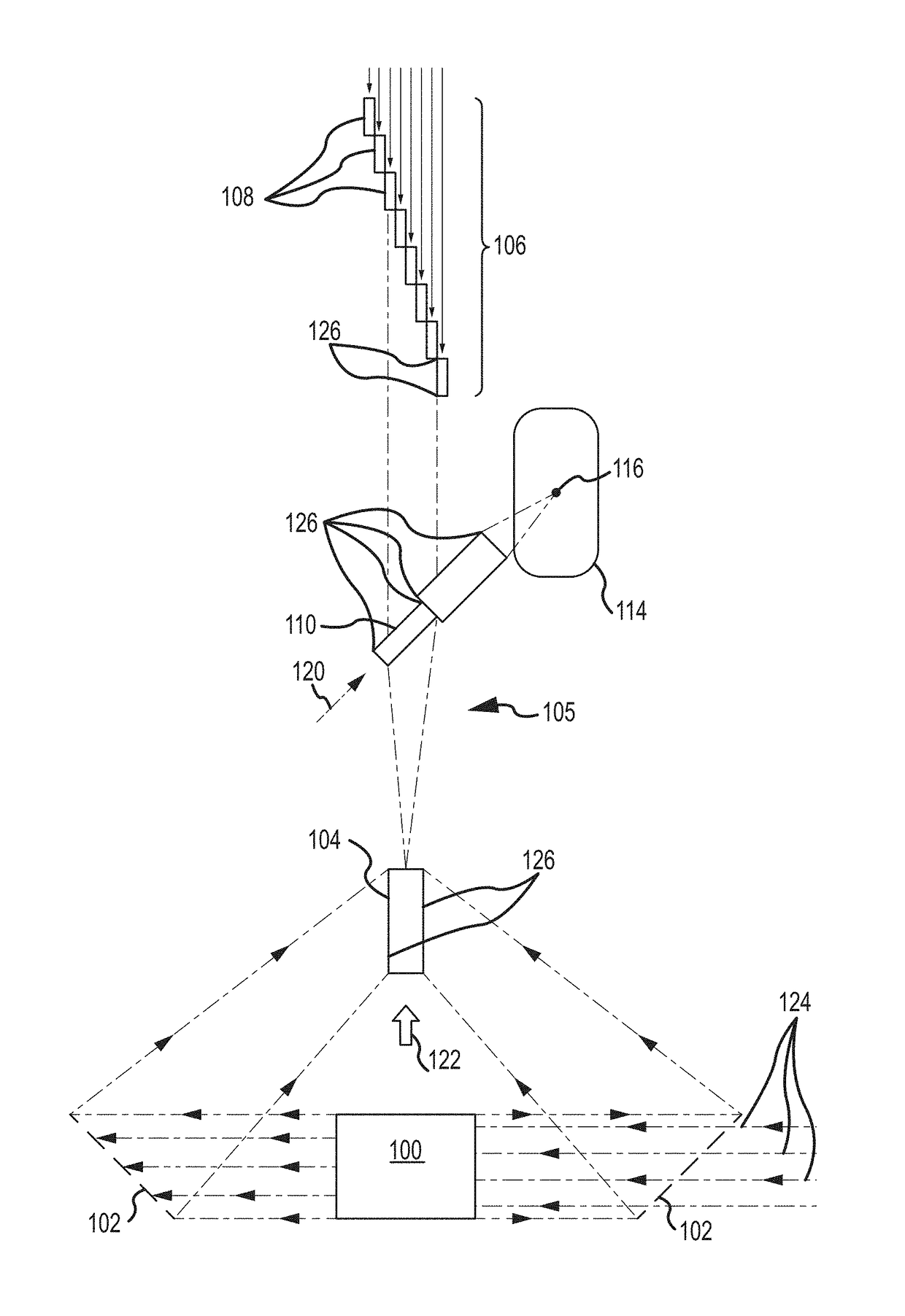
[0081]FIG. 14 shows the layout of a first embodiment in a form emphasizing the partition of elements into their operating or ambient environment. Primary Laser Source [134] which may include Large Pump Module [100] and Turning Array [102, not shown] may be located in air as may be all seed laser sources [136] subsequently amplified by the Primary Laser Source, Raman Converter, Time Delay Mirrors or Fast Compressor. Seed laser beam paths may utilize higher optical quality (especially the Fast Compressor inputs), and may be isolated in stable temperature paths separated by an enclosure from ambient air. Some of these seed laser paths could also be enclosed in tubes filled with N2. Inputs to the Raman Aperture Converter [104] may be located in air (shown more clearly as shutters [126] on the Raman Aperture Converter in FIG. 15). FIG. 15 also shows an example of the input to the Raman Aperture Converter (seed laser input) as a window but could also be shutter(s). Returning to FIG. 14, t...

second embodiment

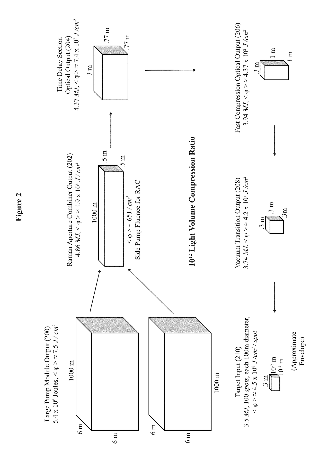
[0096]In FIGS. 6 and 16, High Fluence Material Mirrors [600] are used in the Time Delay Section [106]. The energy and overall pulse length parameters of the Large Pump Module [100] and the Raman Aperture Combiner [104] may be the same as in the exemplary embodiment. The Raman Aperture Combiner Optical Output [202] may be altered to match this type of mirror. The number of compression channels may be increased to 130, for example. The Raman Aperture Combiner Optical Output [202] fluence is 1.8×10⁷ joules / m2, with a total energy of 4.5×10⁶ joules. The size of the High Fluence Material Mirrors [600] may be 0.5 m×0.5 m for a total area of 32.5 m2, for example. This may give an average mirror fluence of 1.38×10⁵ joules / m2, or, 13.8 joules / cm2 for a 2.3×10⁷ second pulse length. Table II, based on “High Damage Threshold Al2O3 / SiO2 Coatings for Excimer Lasers,” supra, may give high reflectivity mirror coating damage levels of 13 joules / cm2 and 27 joules / cm2 for fresh and conditioned halide ...

third embodiment

[0097]FIGS. 7 and 9 are based on a direct high compression arrangement. This embodiment has a high fluence propagation through a helium and / or neon gas in the Time Delay Section [106] and can operate at very high fluence. Some embodiments have the number of time multiplexing channels at 102, and the Active Time Delay Mirrors [108] compression ratio is 15, giving a 2×10⁻⁹ second pulse onto target. To facilitate optical performance, one can make the Backward Raman Mirror Inputs to Active Time Delay Mirrors [118] phase coherent with adaptive optics. The target pattern can be phase impressed in the low power region before the Active Time Delay Mirrors [108]. This may deliver 3.6×10⁶ joules to the target per beamline, for example. This embodiment is very compact, and has few elements. Note that the Fast Compressor [110] may be eliminated.


PUM


Abstract

Embodiments include an optical configuration of a laser for driving an inertial confinement target that may include a section configured to generate long pulse laser light (Primary Laser Source) and then to compress the long pulse with multiple compression stages to a desired pulse length, energy, and beam quality (Compression Section). These configurations can utilize compression stages that do not include any material optics operating near damage fluence, and that do not require material optics exposed to high fluences to couple compression stages to each other.

Description

CROSS-REFERENCE TO RELATED APPLICATION[0001]This application claims priority to U.S. Provisional Patent Application Ser. No. 62 / 497,908 titled “Optical Configurations for Fusion Laser” filed on Dec. 6, 2016, and hereby incorporated by reference.BACKGROUND[0002]This invention relates to a new design for lasers. A major application is a low-cost driver for inertial confinement fusion (ICF) as an energy source, and more particularly, for providing the required very large laser energy in a short optical pulse at low cost.[0003]Over the past approximately 45 years, a substantial effort has been generally directed towards obtaining thermonuclear fusion energy from targets irradiated by various types of particle beams. Lasers, particularly those with short wavelength light (0.25-0.5 microns), have generally emerged as the main contender for producing ignition (substantially more fusion energy out than the energizing beam puts in). The glass laser, where the laser energy is stored in a soli...

Claims


Application Information

Patent Timeline
IPC IPC(8): H01S3/00H01S3/102H01S3/10H01S3/108H01S3/08H01S3/094
CPCH01S3/0057H01S3/1024H01S3/10084H01S3/1086H01S3/0805H01S3/094061G21B1/03G21B1/23H01S3/005H01S3/0071H01S3/0092H01S3/2383H01S3/30Y02E30/10
Inventor HUNTER, JR., ROBERT O.
Owner INNOVEN ENERGY
Why Eureka
Try Eureka