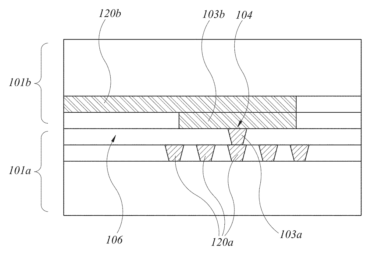
Increased contact alignment tolerance for direct bonding
a direct bonding and alignment tolerance technology, applied in the direction of electrical equipment, semiconductor devices, semiconductor/solid-state device details, etc., can solve the problems of high defect density of hetero-epitaxial grown films, dislocation generation, debonding or cracking, and difficult optimization of process design needed to produce different functions on the same chip containing different materials
- Summary
- Abstract
- Description
- Claims
- Application Information
AI Technical Summary
Benefits of technology
Problems solved by technology
Method used
Image
Examples
second embodiment
[0082]FIGS. 3A-3C are schematic drawings of a process by which two different fully processed dies are bonded. The dies are shown to have planar but uneven layer thickness, to demonstrate that the disclosed embodiments may be used in other instances other than even and planar layer thicknesses. In this process, as shown in FIG. 3A, a separate die 30 (only the oxide layer of die 30 is shown, for convenience of explanation) has metal pads 31. The die may be a silicon wafer including semiconductor devices and circuits have opposing surfaces of SiO2. Surface 32 results after a CMP operation.
[0083]As shown in FIG. 3B, vias 36 have been formed and filled with metal to connect with metal pads 31, metal interconnects 33 are formed on wafer 30 to connect with the metal in vias 36, and a layer 34 of thickness t2, of SiO2 or other insulating material is formed on wafer 30. Portions 35 of the SiO2 layer having a width w2 have been removed to expose metal pads 35. The surface of layer 34 is trea...
first embodiment
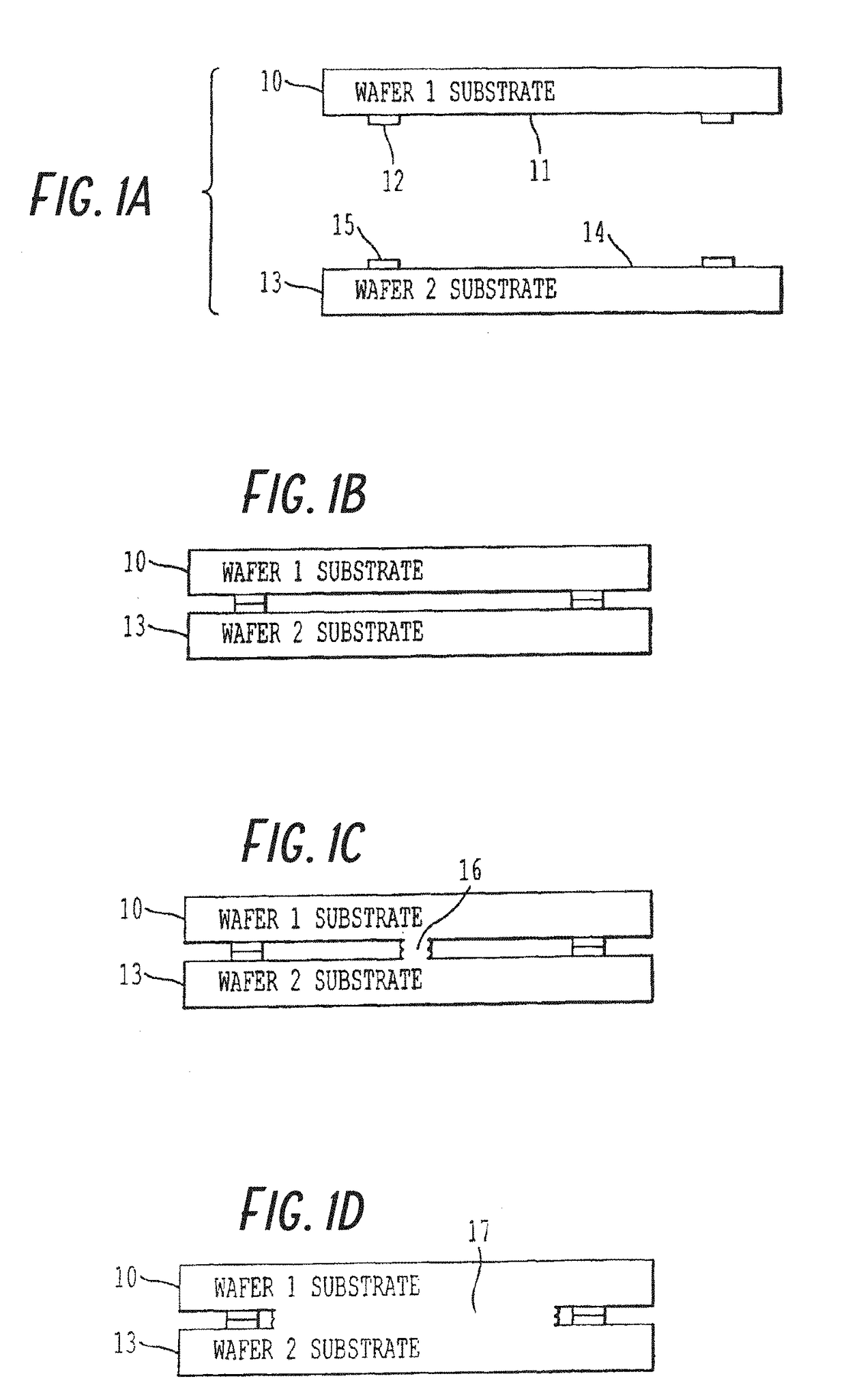
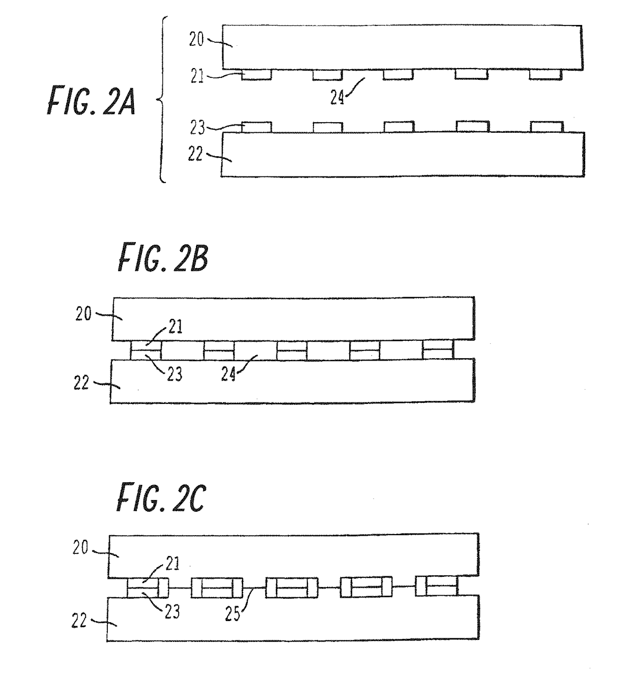
[0086]As in the first embodiment, wafer surfaces 32 and 41 including metal pads 33 and 40 contact, the contacting non-metal (e.g., semiconductor or insulator) parts of opposing wafer surfaces 32 and 41 began to form a bond at the contact points, and the bonding force increases as the contact bonding area increases. Without the presence of protruding metal pads 33 and 40, the wafers would bond across the entire wafer surface. The presence of protruding metal pads 33 and 40, while interrupting the bonding seam between the opposing wafers, does not prohibit wafer to wafer bonding. Rather, the pressure generated by the wafer-to-wafer contact in the non-metal regions translates into a force by which metal pads 33 and 40 are contacted even without any external pressure.
[0087]The method can be carried out in ambient conditions rather than being restricted to high or ultra-high vacuum (UHV) conditions. Consequently, the method is a low-cost, mass-production manufacturing technology. The siz...
third embodiment
[0104]A third embodiment allows a significant increase in the metal height above the non-metal surface and / or significant reduction in non-bonded area near the metal while maintaining an acceptable electrical connection between metal portions formed on separate wafers. In this embodiment, deformation of material in the vicinity of the metal material that forms the electrical contact is designed to result from the pressure at the metal surfaces from the wafer-to-wafer chemical bonding of the non-metal portions. This deformation may result in less pressure applied to the metal after the bonding process is complete, but adequate pressure to form an acceptable electrical connection between the metal portions. This deformation allows the gap near the metal surfaces to be significantly reduced or eliminated.
[0105]The object of the deformable material in the vicinity of the metal material forming the electrical contact is to allow the pressure generated by the chemical bonding of the non-m...
PUM
 Abstract
Description
Claims
Application Information
 - R&D
- Intellectual Property
- Life Sciences
- Materials
- Tech Scout
- Unparalleled Data Quality
- Higher Quality Content
- 60% Fewer Hallucinations
Browse by: Latest US Patents, China's latest patents, Technical Efficacy Thesaurus, Application Domain, Technology Topic, Popular Technical Reports.
© 2025 PatSnap. All rights reserved.Legal|Privacy policy|Modern Slavery Act Transparency Statement|Sitemap|About US| Contact US: help@patsnap.com


