
Gas-steam combined cycle centralized heat supply device and heat supply method

Active Publication Date: 2018-08-09
TSINGHUA UNIV
View PDF1 Cites 13 Cited by
  • Summary
  • Abstract
  • Description
  • Claims
  • Application Information

AI Technical Summary

Benefits of technology

The present invention is a gas-steam combined cycle centralized heat supply device and method that can recover power plant waste heat, improve energy utilization efficiency, and reduce energy consumption and environmental pollution. The invention utilizes various apparatuses such as direct contact type flue gas condensation heat exchanger, steam type absorption heat pumps, and water-water heat exchangers to recover flue gas and exhaust steam waste heat, reduce exhaust flue gas temperature, and improve environmental pollution. The invention also utilizes hot water type absorption heat pumps and water-water heat exchangers in the thermal station to effectively utilize heat of high-temperature supply water and simultaneously heat user supply water, achieving comprehensive energy utilization improvement. Overall, the invention can be widely applied in the power plant waste heat recovery industry.

Problems solved by technology

The current gas-based cogeneration centralized heat supply device mainly has the following problems: (1) Heat-to-electricity ratio is low.
The low heat-to-electricity ratio means low heat supply efficiency.
Consequently, not only is environmental pollution caused, but also an influence is caused to heat supply safety.
(2) Energy loss is great.
(3) Environmental-friendly and landscape effects are poor.
As described above, the consumption of a great amount of gas inevitably causes the emission of a great amount of pollutants.
In addition, a great amount of water vapor contained in the flue gas causes a scene that a chimney discharges “white smoke”, the environment is polluted and the landscape effect is poor.

Method used


Image

  • Gas-steam combined cycle centralized heat supply device and heat supply method
  • Gas-steam combined cycle centralized heat supply device and heat supply method
  • Gas-steam combined cycle centralized heat supply device and heat supply method

Examples


Embodiment Construction

[0026]The present invention will be described below in detail in combination with the drawings and the embodiments.

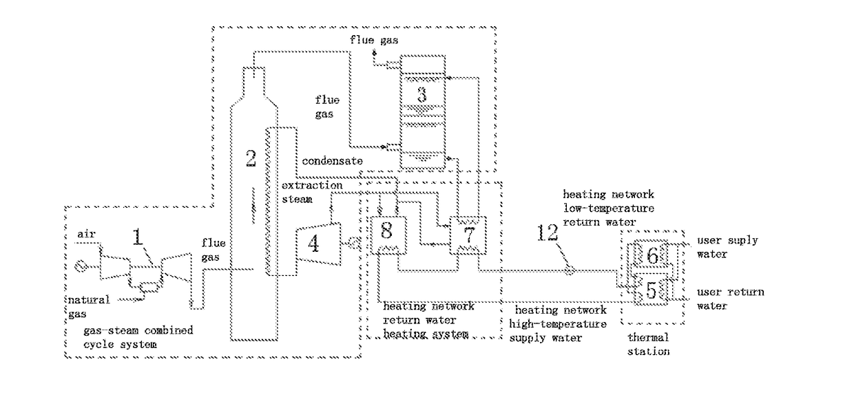
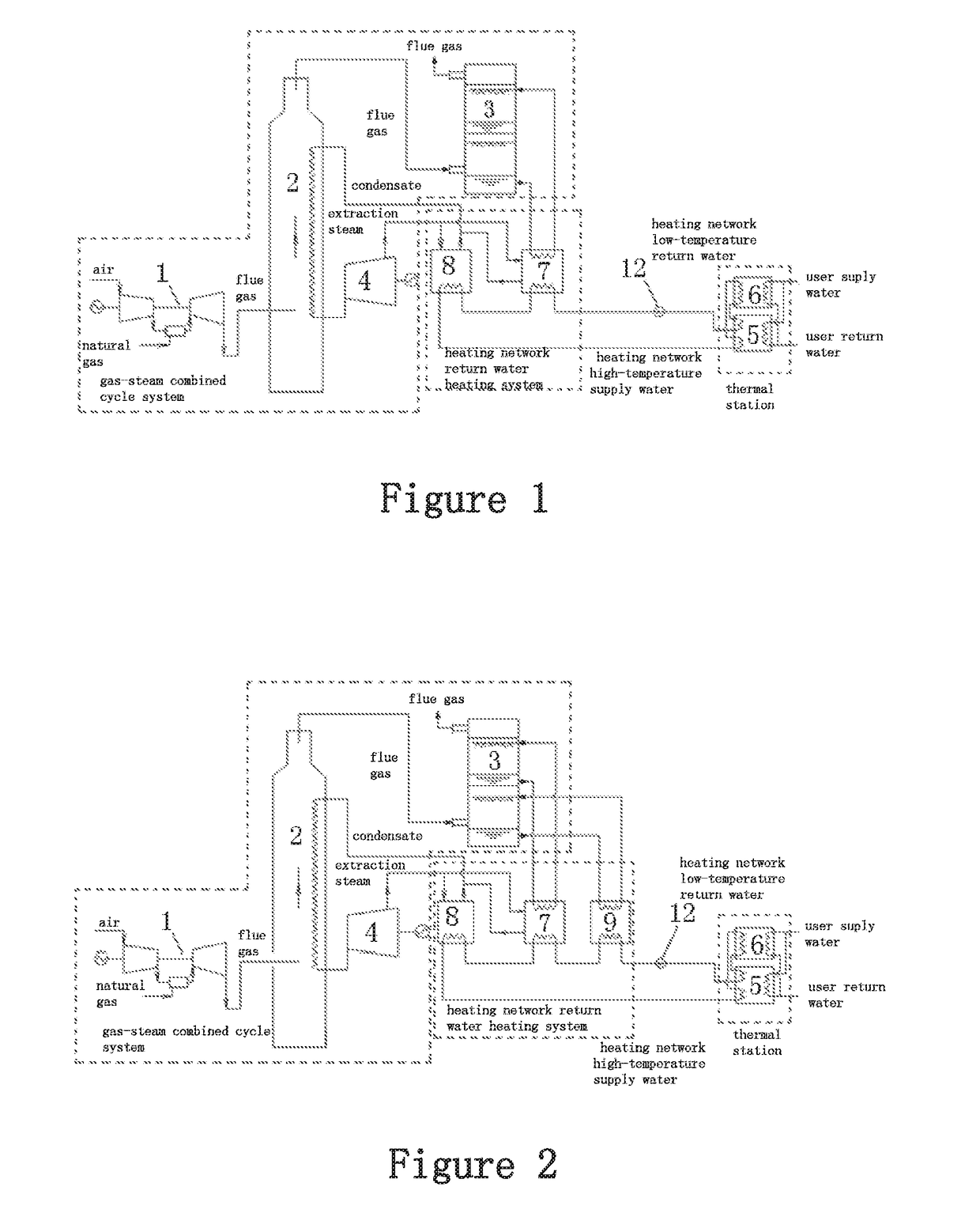
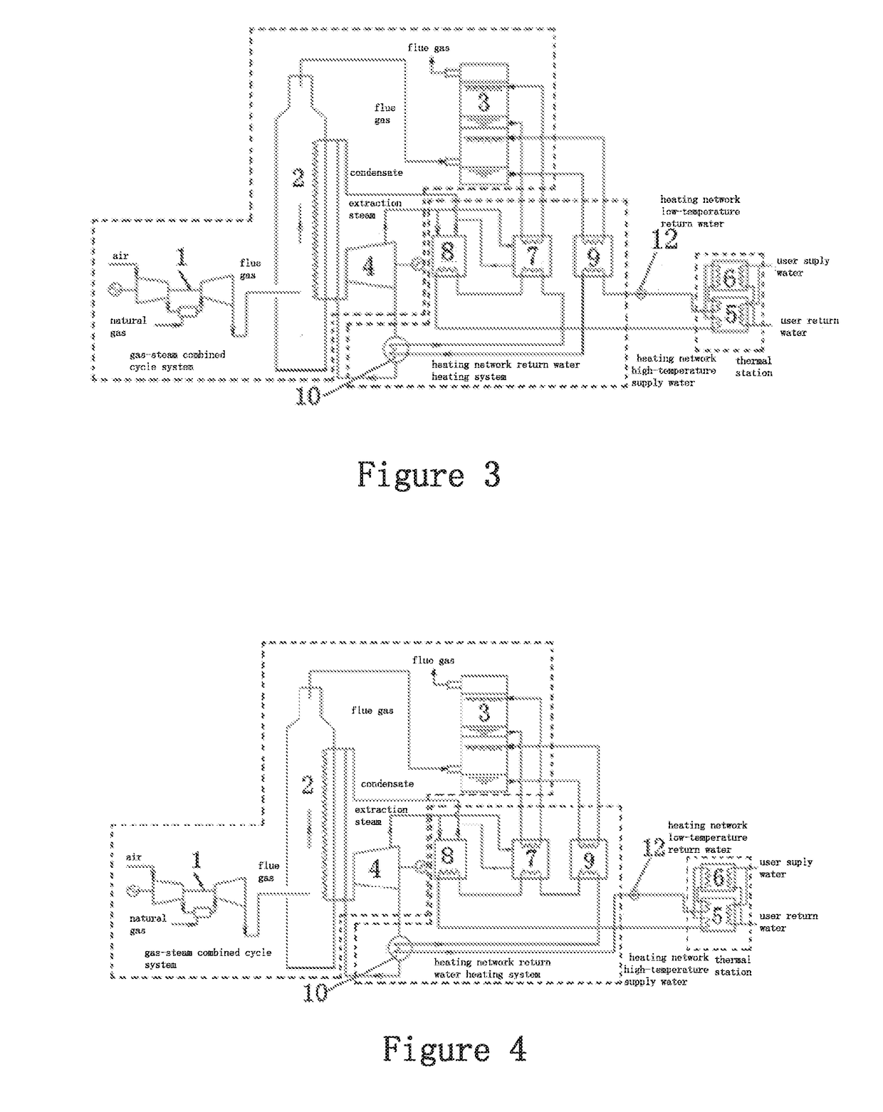
[0027]As shown in FIG. 1, the present invention provides a gas-steam combined cycle centralized heat supply device, which comprises a gas-steam combined cycle system, a thermal station and a heating network return water heating system; and the gas-steam combined cycle system is connected with the thermal station through the heating network return water heating system.

[0028]The gas-steam combined cycle system comprises a gas turbine 1, a waste heat boiler 2, a direct contact type flue gas condensation heat exchanger 3 and a steam turbine 4. An exhaust port of the gas turbine 1 is connected with a flue gas inlet of the waste heat boiler 2. A flue gas outlet of the waste heat boiler 2 is connected with a flue gas inlet of the direct contact type flue gas condensation heat exchanger 3, an steam outlet of the waste heat boiler 2 is connected with an extraction steam inlet of...


PUM


Abstract

The present invention relates to a gas-steam combined cycle centralized heat supply device and a heat supply method. The gas-steam combined cycle centralized heat supply device comprises a gas-steam combined cycle system connected with a thermal station through a heating network return water heating system; the gas-steam combined cycle system comprises a gas turbine connected with a direct contact type flue gas condensation heat exchanger and a steam turbine via a waste heat boiler; the thermal station comprises a hot water type absorption heat pump and a water-water heat exchanger; the heating network return water heating system comprises a steam type absorption heat pump for recovering flue gas waste heat and a steam-water heat exchanger. The present invention can be widely applied to the industry of power plant waste heat recovery.

Description

FIELD OF THE INVENTION[0001]The present invention relates to a heat supply device and a heat supply method, in particular to a gas-steam combined cycle centralized heat supply device and a heat supply method.BACKGROUND OF THE INVENTION[0002]Gas-based cogeneration is an energy utilization form for simultaneously producing heat energy and electric energy. It uses high-grade heat energy for generating power and uses low-grade heat energy for supplying heat, such that not only can the utilization efficiency of energy be improved, but also the environmental pollution is reduced. Natural gas is high calorific value clean energy, greenhouse gas and other harmful substances produced during combustion are far fewer than that of other fossil energy, and thereby natural gas cogeneration has a very great application value in the aspect of reducing carbon and emissions which pollute air.[0003]The current gas-steam combined cycle cogeneration system mainly consists of a gas-steam combined cycle (...

Claims


Application Information

Patent Timeline
IPC IPC(8): F01K17/02F01K23/10
CPCF01K17/025F01K23/10F01K7/16F01K11/02Y02E20/14Y02E20/16Y02E20/18F24D3/18F24D17/0005F24D17/02F28D21/0014Y02T10/12
Inventor FU, LINZHAO, XILINGLI, FENGZHANG, SHIGANG
Owner TSINGHUA UNIV
Learn More