Micropatterned intraocular implants

a micro-patterned, intraocular technology, applied in the field of intraocular implants, can solve the problems of postoperative intraocular pressure spikes, difficult to treat, irreversible amblyopia, etc., and achieve the effects of reducing the travel of the intraocular implant, and reducing the size of the sli

Inactive Publication Date: 2018-08-16
UNIV OF FLORIDA RES FOUNDATION INC +2
View PDF4 Cites 0 Cited by
  • Summary
  • Abstract
  • Description
  • Claims
  • Application Information

AI Technical Summary

Benefits of technology

[0141]Now referring primarily to FIGS. 9 and 10, particular embodiments can, but need not necessarily, have a plurality of patterned surface elements (28) coupled to the external surface (67) of the intraocular implant (18), such as the front surface (22), whether in whole or in part, or the back surface (23) of the intraocular implant (18). As to particular embodiments, the patterned surface elements (28) can be adapted to engage the surface of the posterior capsule (13) to reduce travel of the intraocular implant (18) or maintain the alignment of the center of the intraocular implant (18) with the visual axis (15) of the eye (1),(8). The plurality of patterned surface elements (28) can, but need not necessarily, provide an irregular or uniform pattern, texture, or roughness sufficient to fix or reduce travel of the intraocular implant (18) in the posterior capsule (13). As to certain embodiments of the intraocular implant (18), the plurality of patterned surface elements (28) can, but need not necessarily, provide pockets (29) that function to provide a localized space to deliver or sequester an amount of an active agent (30). The intraocular implant (18) and the plurality of pattern surface elements (28) can be one piece or the plurality of patterned surface elements (28) can be applied to the intraocular implant (18) as a patterned surface element layer (31).
[0142]Now referring primarily to FIGS. 11 through 12, and 16 through 18, particular embodiments of the flexible membrane (19) can, but need not necessarily include, one or more radial slit elements (32) cut through the thickness (24) of the flexible membrane (19). As to particular embodiments, the radial slit elements (32) originate at the outer boundary (20) and cut a distance radially toward the center of the flexible membrane (19) (as shown in the examples of FIG. 11). The one or more radial slit elements (32) can have sufficient slit length (34) and slit width (33) to allow the flexible membrane (19) to conform to a g...

Problems solved by technology

However, there may be substantial problems with this procedure such as IOL (11) damage, postoperative intraocular pressure spikes, vitreous floaters, cystoid macular edema, retinal detachment, and IOL (11) subluxation, or the like.
Additionally, pediatric patients can be difficult to treat and a delay in treatment can lead to irreversible amblyopia.
Many underdeveloped countries do not have access to a Nd:YAG laser and the cost can be prohibitive.
Additionally, the majority of pharmacological agents tested in-vitro for inhibition of migration and proliferation of LECs (16) are antimetabolites and antimitotics, which have not been used clinically because of their toxic side effects.
Problems relating to incomplete seal of the lens capsule (7) resulting in leakage of potentially toxic chemicals into the anterior chamber (17) of the pseudophakic eye (8), rupture of the lens capsule (7) during manipulation of the irrigation device, difficulty in assessing kill of LECs (16) within the lens capsule (7), and an increase in the duration of routine cataract surgery limit the usefulness of the irrigation device.
Another prominen...

Method used


Image

  • Micropatterned intraocular implants
  • Micropatterned intraocular implants
  • Micropatterned intraocular implants

Examples


example 1

[0215]Now referring primarily to FIGS. 39 through 42, smooth and patterned flexible membranes (19) were fabricated by casting biomedical grade polydimethylsiloxane elastomer (“PDMSe”, SILASTIC® MDX4-4210; Dow Corning, Midland, Mich.) against negative silicon wafer molds. The flexible membranes (19) produced by this method included a plurality of patterned surface elements (28) and non-linear channel elements (71) arranged in a pattern (72) as shown in the examples of FIGS. 39 through 42 that either protruded from the surface of the PDMSe flexible membrane (19) as shown in the example of FIGS. 39 and 40 or were recessed into the PDMSe flexible membrane (19) as shown in the examples of FIGS. 41 and 42. A pattern (72) with patterned surface elements (28) protruding 3 μm from the surface of the flexible membrane (19) that were 2μm wide and spaced by 2 μm would be called +3SK2×2. The patterns (72) replicated for testing included smooth unpatterned “SM”, −3SK2×2, +3SK2×2, and +7SK10×5.

[02...

example 3

[0218]Now referring primarily to FIGS. 81A through 81D and 82, circular flexible membranes (19) (diameter=about 20 mm) including “SM”, −3SK2×2, +3SK2×2, and +7SK10×5 samples were adhered to a 12-well plate with the axis A′-A′ (101) of the plurality of groups of surface elements (78) of the −3SK2×2, +3SK2×2, and +7SK10×5 samples aligned orthogonal to the direction of cell adhesion, growth, or migration (107) and treated with 15 μg / mL fibronectin (BD Biosciences, San Jose, Calif.) in phosphate buffered saline (Life Technologies, Carlsbad, Calif.) overnight to facilitate cell attachment. A modified scratch-wound assay was created by blocking cell attachment to the samples using SM PDMSe rectangles (3 mm×320 mm) placed along the center of the flexible member (19) to simulate wound areas (140). LECs (16) (ATCC CRL-11421; ATCC, Manassas, Va.) were seeded over the entire assembly at 1×10⁴ cells / cm2 and maintained in growth media (Eagle's Minimum essential media; ATCC), 20% fetal bovine ser...

example 4

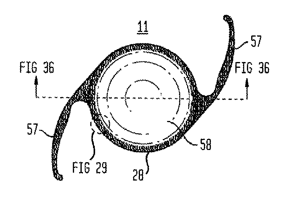
[0219]Now referring to FIGS. 22 through 30, steel casting molds were designed and machined by 103 MicroStructures (Wheeling, Ill.) for prototype intraocular implant (18) production. Intraocular implants (18) (as shown by the examples of FIGS. 22 through 30) were replicated in PDMSe and sterilized by immersion in 70% ethanol in water (vol / vol) prior to use. Intraocular implants (18) were designed with a generally circular annular member (50) (outer annular surface (52) diameter of about 9.5 mm). A thin flexible membrane (19) (thickness (24) of about 0.1 mm) spanned the area between the annular member (50) and an aperture element (26) providing a visual axis (15) for the optical lens (58) (diameter of 5.5 mm) of an IOL (11). The inner annular surface (51) of the annular member (50) had an annular inner surface height (56) of about 1.2 mm to which the haptics (57) of the IOL (11) were engaged to retain the IOL (11) within the intraocular implant (18). The flexible membrane (19) was des...


PUM


Abstract

Generally, an intraocular implant having on the external surface a plurality of pattern surface elements disposed in spaced apart relation defining a tortuous pathway adapted to control a flow of fluid or a flow of particles suspended in a fluid or inhibit the growth or migration of cells is provided. In particular, an intraocular implant that is implanted between an intraocular lens and the surface of the posterior capsule of the eye inhibits growth or migration of residual lens epithelial cells after cataract surgery by providing structural barriers to reduce posterior capsule opacification of the eye.

Description

CROSS-REFERENCE TO RELATED APPLICATIONS[0001]This United States Patent Application is a continuation in part application of U.S. patent application having Ser. No. 14 / 821,645 filed on Aug. 7, 2015, claiming the benefit of priority of U.S. Provisional Patent Application 62 / 034,401, filed Aug. 7, 2014, and is a continuation-in-part of U.S. patent application Ser. No. 14 / 298,318, filed Jun. 6, 2014, which is a continuation of U.S. patent application Ser. No. 13 / 944,817, filed Jul. 17, 2013, which is a continuation of U.S. patent application Ser. No. 13 / 479,178, filed May 23, 2012, which is a continuation-in-part of U.S. patent application Ser. No. 13 / 136,515, filed Aug. 2, 2011, now U.S. Pat. No. 8,551,167, issued Oct. 8, 2013, which is a continuation-in-part of U.S. patent application Ser. No. 12 / 998,652, filed May 13, 2011, which is a United States National Stage of International Patent Cooperation Treaty Patent Application No. PCT / US2009 / 006195, filed Nov. 19, 2009, which claims the...

Claims


Application Information

Patent Timeline
IPC IPC(8): A61F2/16A61F2/14A61L27/58A61L27/38A61F2/00
CPCA61F2/0077A61F2002/009A61F2/14A61L2430/16A61F2/161A61F2/16015A61L27/3869A61F2/15A61F2/1624A61F2002/0081A61F2002/1681A61L27/58A61F2/16A61F2/1613A61F9/0017
Inventor CUEVAS, KEVIN H.REDDY, SHRAVANTHI T.MAGIN, CHELSEA MARIEMETTETAL, MICHAEL R.BRENNAN, ANTHONY B.MAY, RHEA MARIEMANN, ETHAN EUGENE
Owner UNIV OF FLORIDA RES FOUNDATION INC
Why Eureka
Try Eureka