
Sliding member

a technology of sliding member and sliding plate, which is applied in the direction of sliding contact bearing, superimposed coating process, transportation and packaging, etc., can solve the problems of reduced bonding strength, increased peeling, and reduced bonding strength between copper alloy and back metal, so as to increase the strength of a copper alloy and reduce the surface area. , the effect of increasing the strength

Active Publication Date: 2018-09-13
DAIDO METAL CO LTD
View PDF3 Cites 5 Cited by
  • Summary
  • Abstract
  • Description
  • Claims
  • Application Information

AI Technical Summary

Benefits of technology

The patent text describes a method for improving the bonding strength between a copper alloy layer and a substrate. The method involves reducing the amount of solid-dissolved tin and deposited intermetallic compounds through a heating process. The copper alloy layer formed on the substrate has a reduced amount of tin at the interface with the substrate, increasing the bonding strength and reducing the possibility of peeling. The method can be used to create a sliding material with improved strength and durability.

Problems solved by technology

For a sliding material including a high strength (lesser toughness) copper alloy sliding layer on a back metal, a shearing stress generated during sliding tends to concentrate at an interface between the copper alloy and the back metal, and a possibility of peeling is increased.
However, a bonding strength between the copper alloy and the back metal can not be increased at the same time.
However, a rate of solidification shrinkage of the copper alloy is increased and high peeling strength between the copper alloy and the steel is generated so that a bonding strength is reduced.

Method used


Image

  • Sliding member
  • Sliding member
  • Sliding member

Examples


examples

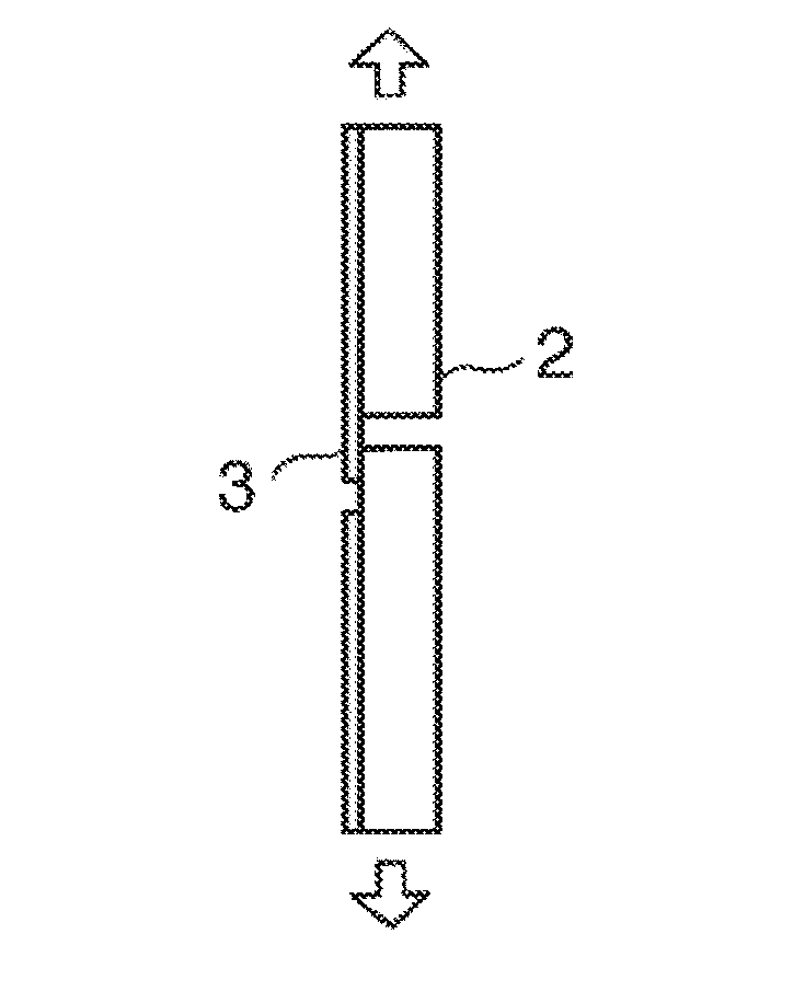
[0061]Examples 1 to 21 of the invention and comparison examples 1 to 5 were produced and the gradient region and the bonding strength were evaluated.

[0062]Preparation of the Substrate

[0063]A plate made of a steel SPCC was used as a substrate, and an upper surface of the steel plate was scraped at a central area with remaining all side to produce an open box-shape which has dams at all sides to prevent leakage of a molten alloy. A thickness for the cast was designed to be 5 mm. A thickness of an area to become the substrate of the sliding material was designed to be 6 mm. The surface of the substrate was covered by molten borax as an antioxidant, and the substrate was preheated at a temperature of 1000 to 1200° C. in a reducing H2 gas atmosphere.

[0064]Casting of the Copper Alloy

[0065]Pure copper, pure tin, and other component material / materials were blended according to the compositions of the copper alloys of Examples 1 to 21 and Comparative Examples 1 to 5 in tables 1 and 2, and we...


PUM

PropertyMeasurementUnit
thicknessaaaaaaaaaa
thicknessaaaaaaaaaa
thicknessaaaaaaaaaa

Abstract

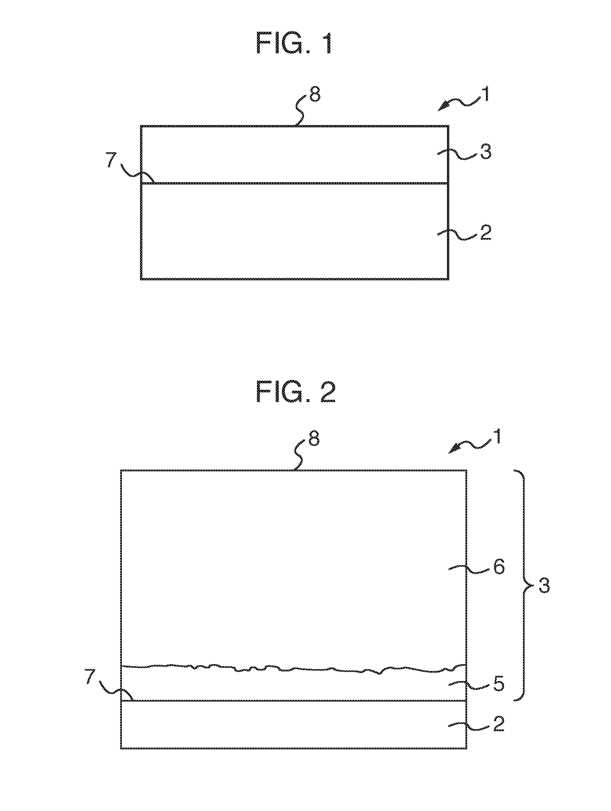
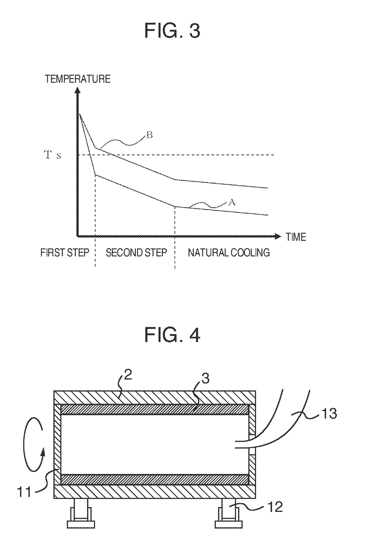
Provided is a sliding material including a substrate; and a copper alloy layer bonded to the substrate. The copper alloy includes 2.0 to 15.0% by mass of tin. The copper alloy layer includes a sliding body part including a sliding surface, and a gradient region including a bond surface with the substrate. A tin concentration in the gradient region reduces from the sliding body part toward the bond surface. A method for producing the siding material is also provided. The method includes preparing the substrate having a first surface and a second surface opposite to the first surface; melting the copper alloy; casting the molten copper alloy on the first surface of the substrate; and solidifying the copper alloy unidirectionally by cooling the substrate from the second surface by a coolant.

Description

FIELD OF THE INVENTION[0001]The present invention relates to a sliding material, in particular, to a sliding material having a copper alloy layer including tin on a substrate. The present invention also relates to a method for producing the sliding material, to a sliding member including the sliding material, and a bearing device.BACKGROUND OF THE INVENTION[0002]Various Sliding members used for internal combustion engines, bushes, or thrust washers have been proposed that includes a back metal coated with a lead-free copper alloy including tin (see e.g. JP 2010-150649 A). The copper alloy including tin has good sliding properties, seize resistance, and wear resistance, since tin enhances strength of the copper alloy to improve the wear resistance as well as improves the corrosion resistance and the sliding properties. A process for sintering a copper alloy powder on the back metal has been employed for coating the copper alloy layer on the back metal (see e.g. JP 8-209264 A).[0003]O...

Claims


Application Information

Patent Timeline
Patent Type & Authority Applications(United States)
IPC IPC(8): F16C33/12B32B15/01B32B15/18B32B15/20B22D19/08B22D27/04C22C9/02C22C9/00F16C17/10
CPCF16C33/121B32B15/015B32B15/18B32B15/20B22D19/085B22D27/045C22C9/02C22C9/00F16C17/10F16C2204/10F16C2360/22B22D19/16C22C32/0084C22C32/0089F16C33/14B22D13/023F16C33/124F16C2202/50F16C2204/12F16C2204/18F16C2223/44F16C2240/60Y10T428/12458Y10T428/12882Y10T428/12903Y10T428/1291Y10T428/12917Y10T428/12924Y10T428/12993Y10T428/2495Y10T428/24967Y10T428/263Y10T428/264Y10T428/265Y10T428/27Y10T428/273C23C28/021C23C28/36C23C30/00C23C30/005
Inventor TODA, KAZUAKI
Owner DAIDO METAL CO LTD
Learn More