
Carbon-silicon composite material, negative electrode, secondary battery, and carbon-silicon composite material producing method

Active Publication Date: 2018-10-18
TECONE
View PDF2 Cites 0 Cited by
  • Summary
  • Abstract
  • Description
  • Claims
  • Application Information

AI Technical Summary

Benefits of technology

The patent text describes a way to create a material that can be used as a negative electrode material in batteries. The material has high capacity, small irreversible capacity, and long cycle life. This means it can hold a lot of lithium, the key ingredient in batteries, and can be charged and discharged many times without losing effectiveness. This material can be useful in making batteries with high energy density and long life.

Problems solved by technology

Addition of a Si particle simple substance as a negative electrode active material, however, causes a large volume change (about 300%) as with inserting (intercalating) / separating of lithium ion.
Further, due to mechanical disruption of Si negative electrode during an alloying / dealloying process thereof, immediate and irreversible reduction in an amount will occur, followed by lowering of coulombic efficiency.

Method used


Image

  • Carbon-silicon composite material, negative electrode, secondary battery, and carbon-silicon composite material producing method
  • Carbon-silicon composite material, negative electrode, secondary battery, and carbon-silicon composite material producing method
  • Carbon-silicon composite material, negative electrode, secondary battery, and carbon-silicon composite material producing method

Examples


example 1

[0157]PVA (product name: POVAL 224, saponification degree: 88 mol %, polymerization degree: 2400, produced by KURARAY CO., LTD.) of 60 pts.mass, carbon black (primary particle size: 35 nm, iron: 1 ppm) of 5 pts.mass, metallic Si (average grain size: 0.4 μm, produced by: KINSEI MATEC CO., LTD.) of 35 pts.mass, and water of 500 pts.mass were mixed by means of a bead mill. A carbon black-metallic Si dispersing liquid (PVA was dissolved) could be obtained.

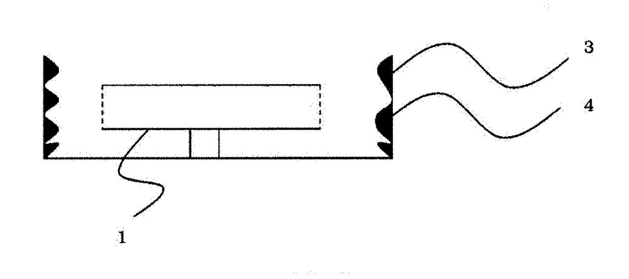
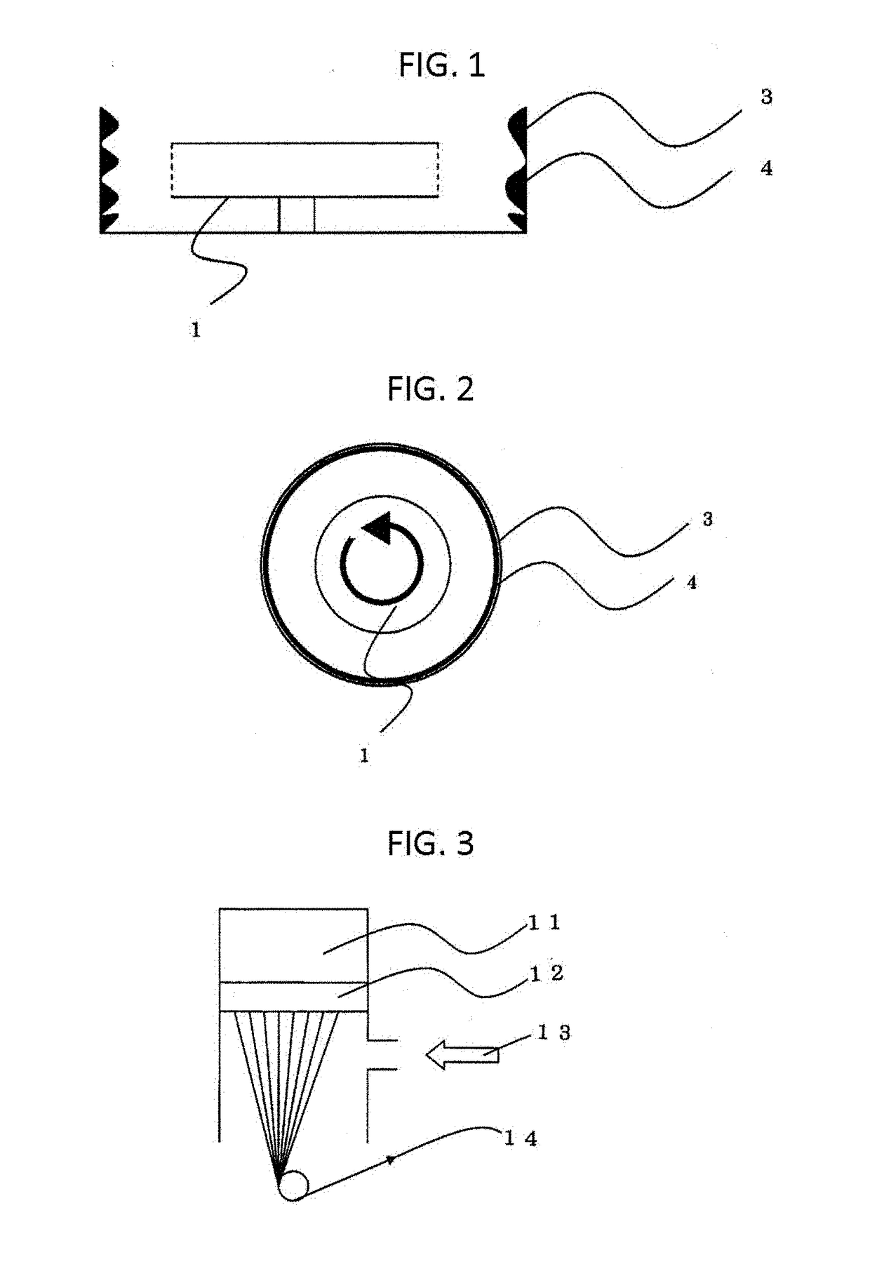
[0158]A centrifugal spinning apparatus (see, FIGS. 1 and 2, distance between nozzle and collector: 20 cm, disk spinning number: 10,000 rpm) was used. The dispersing liquid was used to perform spinning (dehydration) by means of the centrifugal spinning apparatus. A nonwoven fabric (C—Si composite material precursor) was formed on a collection plate.

[0159]The obtained nonwoven fabric was heated (800° C., 1 hour, in a reducing atmosphere).

[0160]The obtained nonwoven fabric (C—Si composite material) was processed by using a mixer. Accordin...

example 2

[0168]Example 2 was performed in a manner similar to that performed in Example 1 except that PVA (saponification degree: 98 mol %, polymerization degree: 2400) of 60 pts.mass, carbon black (primary particle size: 50 nm), and metallic Si (average grain size: 2 μm) were used. A C—Si composite material similar to that obtained in Example 1 could be obtained. The C—Si composite material obtained in the present example was a fiber shaped C—Si composite material (diameter: 5 μm, length: 55 μm). Other characteristics are shown in Table-1.

example 3

[0169]Example 3 was performed in a manner similar to that performed in Example 1 except that carbon black (primary particle size: 35 nm) of 32 pts.mass and metallic Si (average grain size: 0.1 μm) of 8 pts.mass were used. A C—Si composite material similar to that obtained in Example 1 could be obtained. The C—Si composite material obtained in the present example was a fiber shaped C—Si composite material (diameter: 0.5 μm, length: 5 μm). Other characteristics are shown in Table-1.


PUM

PropertyMeasurementUnit
Grain sizeaaaaaaaaaa
Percent by massaaaaaaaaaa

Abstract

The present invention provides a carbon-silicon composite material suitable (e.g., high capacity; small irreversible capacity; long cycle life) to be used as a negative electrode material for battery. The carbon-silicon composite material comprises a carbon black and a silicon particle, wherein the carbon black and the silicon particle are bound via a resin thermolysis product.

Description

TECHNICAL FIELD[0001]The present invention relates to a carbon-silicon (C—Si) composite material.BACKGROUND ART[0002]A silicon (Si) based material is receiving a lot of attention as a negative electrode material for lithium ion battery.[0003]Addition of a Si particle simple substance as a negative electrode active material, however, causes a large volume change (about 300%) as with inserting (intercalating) / separating of lithium ion. This involves progress of disintegrating of a Si particle, resulting in inviting a short cycle life. Further, due to mechanical disruption of Si negative electrode during an alloying / dealloying process thereof, immediate and irreversible reduction in an amount will occur, followed by lowering of coulombic efficiency.[0004]A C—Si composite material is drawing an attention as a technology capable of solving the above described problem.[0005]JP 2013-534024 A (Patent Literature 1) proposes: for example, “a combined hard carbon anode material for lithium ion...

Claims


Application Information

Patent Timeline
IPC IPC(8): H01M4/36H01M4/587H01M4/38H01M4/62H01M10/0525C04B35/532C04B35/634C04B35/64
CPCH01M4/364H01M4/587H01M4/386H01M4/621H01M10/0525C04B35/532C04B35/63416C04B35/64H01M2004/027H01M2004/021C04B2235/424C04B2235/428C04B2235/48C04B2235/5436C04B2235/526C04B2235/5264C04B2235/786C04B2235/785H01M4/134H01M4/1395H01M4/625H01M10/052Y02E60/10Y02P70/50H01M4/366C01B33/02C01B32/05C01P2004/80
Inventor KITANO, TAKAHIRO
Owner TECONE
Learn More