

Ultrasound Diagnostic Apparatus and an Ultrasound Signal Processing Method
a diagnostic apparatus and ultrasound technology, applied in the field of ultrasound diagnostic equipment and ultrasound signal processing method, can solve the problems of increasing the cost of ultrasound diagnostic equipment, difficult to implement data transfer operation with inexpensive hardware, and high hardware cost, etc., to reduce the computation amount of delay-and-sum and data amount of acoustic line signal, suppress the degradation of spatial resolution and s/n ratio, and reduce the internal memory capacity and data transmission capability. the effect of the necessary capacity
- Summary
- Abstract
- Description
- Claims
- Application Information
AI Technical Summary
Benefits of technology
Problems solved by technology
Method used
Image

Examples
embodiments
[0045]1. Overall Configuration
[0046]Hereinafter, an ultrasound diagnostic apparatus 100 according to an embodiment will be described with reference to the drawings.
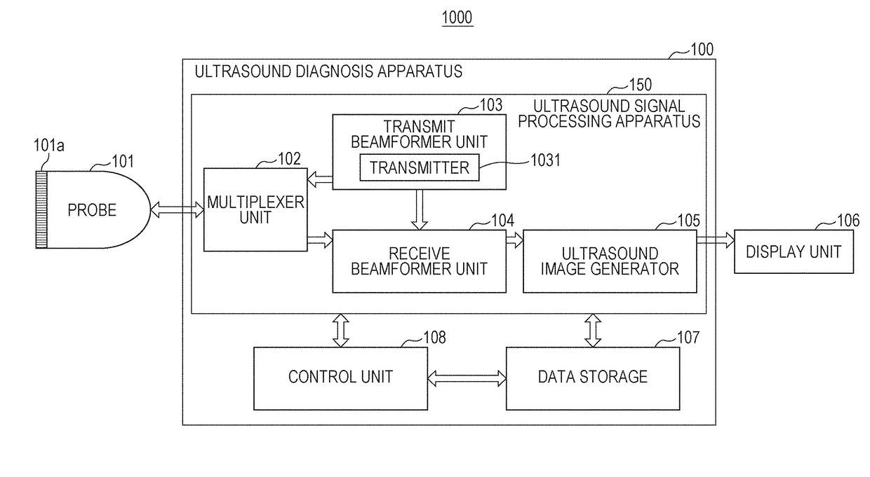
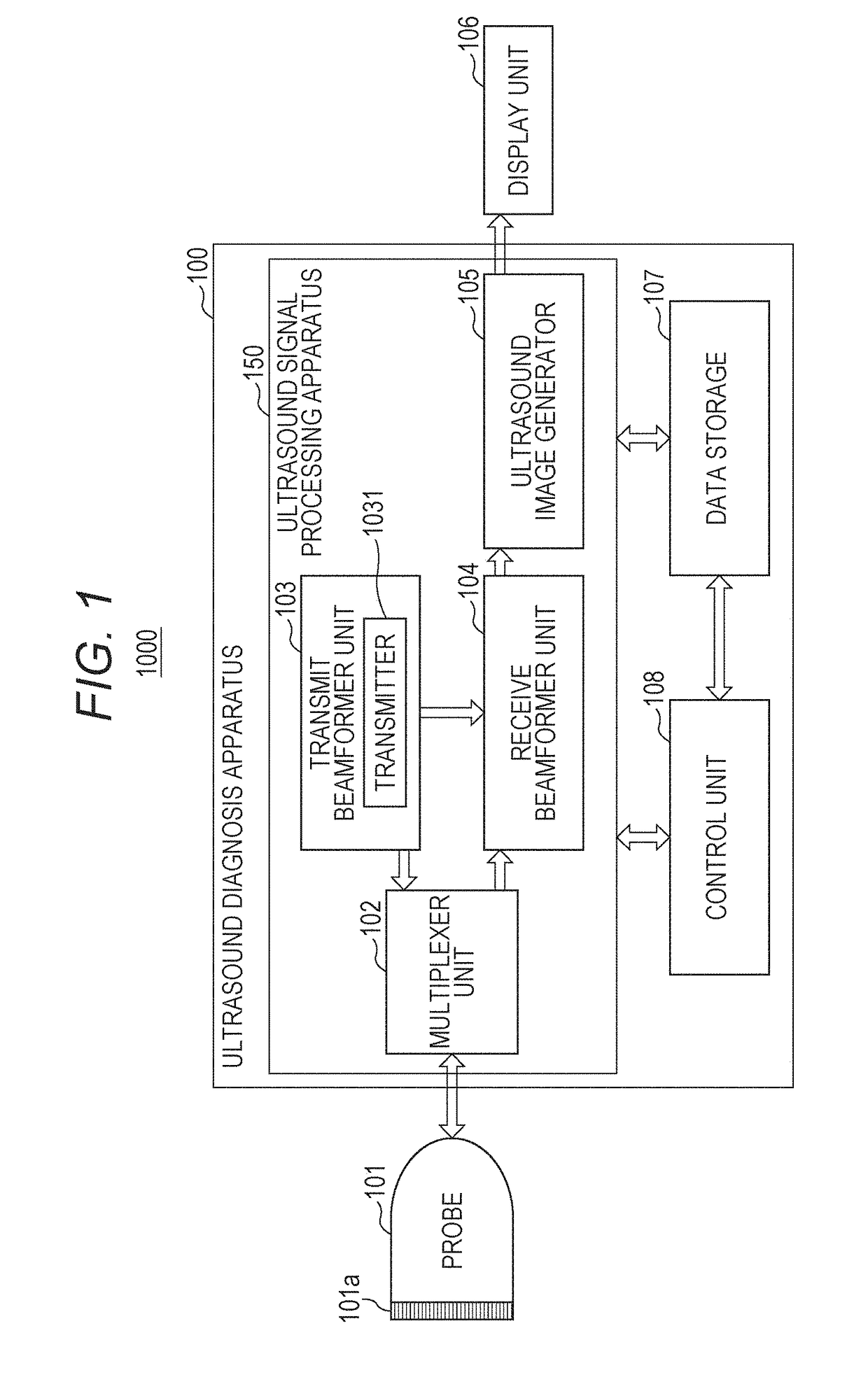
[0047]FIG. 1 is a functional block diagram illustrating a configuration of the ultrasound diagnostic apparatus 100 according to the embodiment. As illustrated in FIG. 1, the ultrasound diagnostic system 1000 includes: an ultrasound probe 101 (hereinafter referred to as “probe 101”) having a plurality of transducers 101a that transmits ultrasound waves toward a subject and receives the reflected waves; an ultrasound diagnostic apparatus 100 that causes the probe 101 to transmit and receive ultrasound waves and generates an ultrasound image on the basis of an output signal from the probe 101; and a display unit 106 that displays the ultrasound image on a screen. The probe 101 and the display unit 106 are each configured to be connectable to the ultrasound diagnostic apparatus 100. FIG. 1 illustrates a state in which the pro...
example 1
[0219]FIG. 23 is a schematic mounting view of the receive beamformer unit 104 in an ultrasound diagnostic apparatus 100A according to an example of the present embodiment. The following is functional arrangement in the receiver 40, the delay-and-sum part 41, and the combiner 42 implemented in each of the plurality of integrated circuits constituting the receive beamformer unit 104 when the division number n of the partial transducer array 101a_1 is 2. As illustrated in FIG. 23, the ultrasound diagnostic apparatus 100A includes the partial transducer arrays 101a_1 and 101a_2 obtained by dividing the transmission transducer 101a array formed with 128 transducers into n (n=2), each including integrated circuits 501_1 and 501_2 connected to 64 transducers (64 channels), and an integrated circuit 501_3. Each of the plurality of part receivers 401_1 and 401_2, each of the plurality of part delay-and-sum parts 411_1 and 411_2, and each of the plurality of part folding parts 412_1 and 412_2...
example 2
[0224]FIG. 24 is a schematic mounting view of the receive beamformer unit 104 in an ultrasound diagnostic apparatus 100B according to another example of the present embodiment. Again, the division number n of the partial transducer array 101a_1 is 2. As illustrated in FIG. 24, the ultrasound diagnostic apparatus 100B has the following configuration. The partial transducer arrays 101a_1 and 101a_2 obtained by dividing the array of the reception transducer 101a into n (n=2) includes n integrated circuits 511 and 512. Each of the plurality of part receivers 401_1 and 401_2, each of the plurality of part delay-and-sum parts 411_1 and 411_2, and each of the plurality of part folding parts 412_1 and 412_2 are included in each of the n integrated circuits 511 and 512, respectively. The summing part 413 and the re-sequence part 414 are included in any of the n integrated circuits 511 and 512. The acoustic line signal partial subframe folded data dsc_1 is transmitted to the integrated circui...
PUM
 Abstract
Description
Claims
Application Information