Non-aqueous electrolyte secondary battery cell and assembled battery using same

Active Publication Date: 2018-11-15
E GLE CO LTD
View PDF2 Cites 2 Cited by
  • Summary
  • Abstract
  • Description
  • Claims
  • Application Information

AI Technical Summary

Benefits of technology

[0030]In the invention as set forth in claim 1, the temperature sensor and voltage sensor of the cell monitoring system are accommodated in the hollow part of the core material in the battery cell, so it is possible to measure the temperature and voltage of the battery accurately. The temperature sensor, in particular, can reliably sense a temperature increase in the cell basic member so as to enable suppression of same, because the temperature sensor is attached to the core material at the central part of the hollow part of the core material by being firmly adhered thereto. Moreover, since there is employed a configuration in which heat generated at the balancer accommodated in the hollow part of the core material is dissipated via the positive electrode or negative electrode terminal, a temperature increase in the battery is suppressed even more reliably.
[0031]The invention as set forth in claim 2 employs a configuration in which a Zener diode that consumes surplus electric power at the time of overcharge is provided in the cell monitoring system, and heat generated at the Zener diode is dissipated via the positive electrode or negative electrode terminal, and therefore, a temperature increase in the battery due to overcharge can be reliably suppressed.
[0032]In the invention as set forth in claim 3, the cell basic member constituted by the positive electrode member, separator, and negative electrode member for the non-aqueous electrolyte secondary battery is wound or laminated on the core material serving as a shaft, and the current collectors of the positive electrode member and the negative electrode member are extended in opposite directions and are connected to the terminals provided on both ends of the core material in a direct, electrical, and heat-conductive manner, whereby a highly efficient, compact structure is achieved.
[0033]In the invention as set forth in claim 4, there is employed a configuration in which f

Problems solved by technology

One of the reasons for which it is impossible to attain high energy density, as described above, is related to safety issues.
When there is liquid leakage, lithium hexafluorophosphate as a solute dissolves in water to emit hydrofluoric acid, which is hazardous because of being toxic to the human organism and also flammable.
The second reason is the possibility of overcharge.
In the state of overcharge, a positive electrode material emits oxygen (O), which may result in catching fire.
The third reason is the possibility of short circuiting.
Occurrence of short circuiting may lead to sudden temperature increase inside the cell, wh

Method used


Image

  • Non-aqueous electrolyte secondary battery cell and assembled battery using same
  • Non-aqueous electrolyte secondary battery cell and assembled battery using same
  • Non-aqueous electrolyte secondary battery cell and assembled battery using same

Examples


exemplary embodiment 1

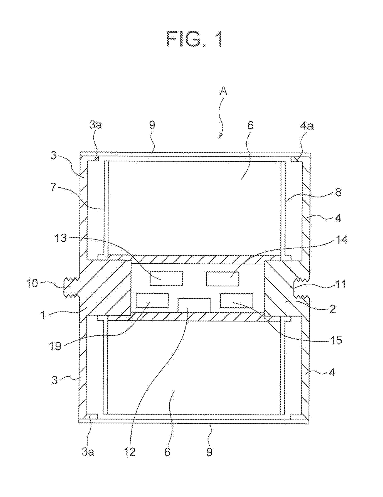
[0049]A non-aqueous electrolyte secondary battery cell A of this invention will be explained on the basis of FIGS. 1 to 8.

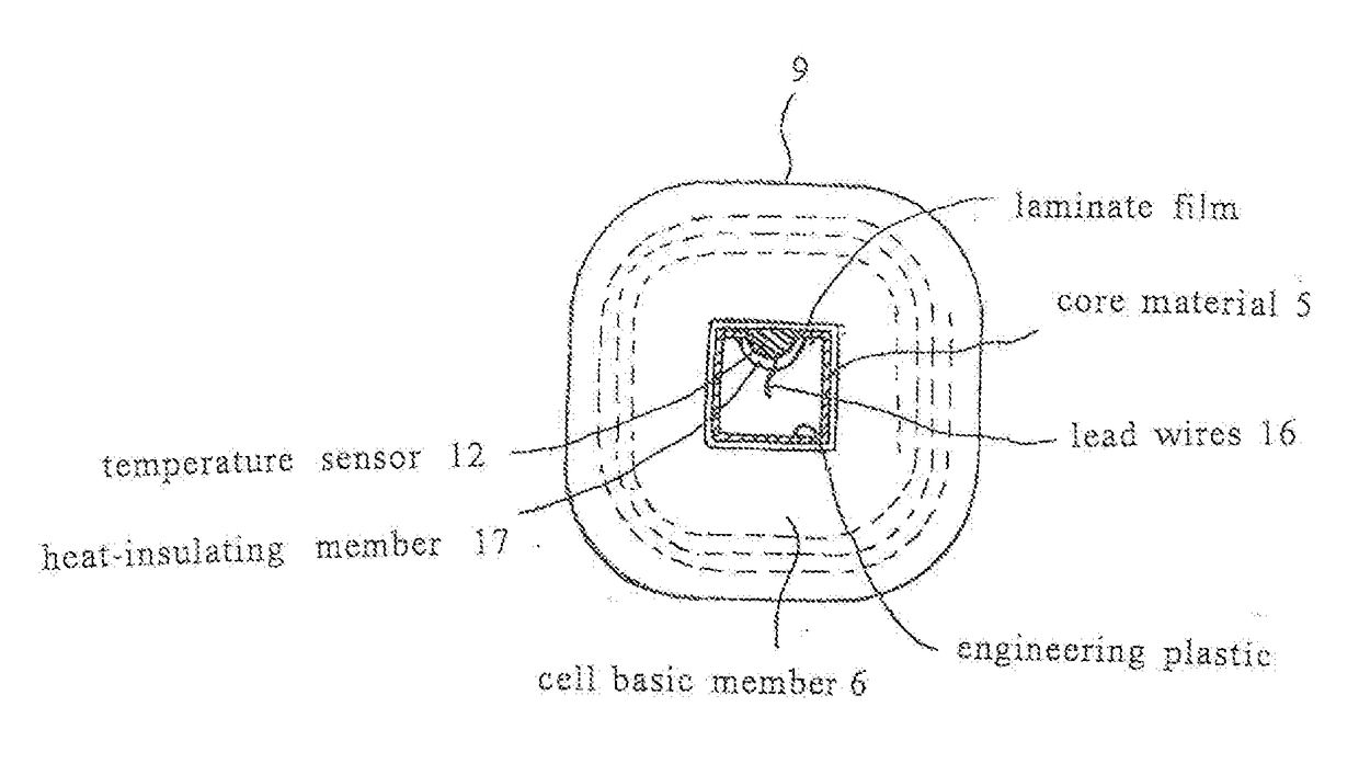
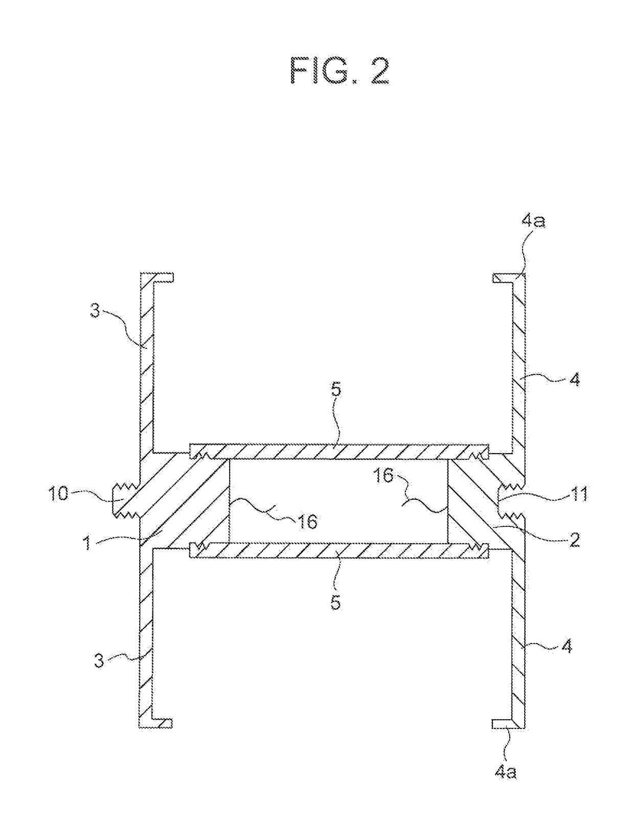
[0050]In the non-aqueous electrolyte secondary battery cell A, two metal plates, each of which has the shape of a quadrangle with rounded corners and is highly electro-conductive, are provided so as to face each other while being spaced apart from each other; central parts of the two metal plates project in swelling fashion and inwardly; a cross section of each of these projections is approximately quadrangular; either one of the projections and the central part of the metal plate, which is contiguous to the projection, serve as either a positive electrode or negative electrode terminal 1 or 2; and portions of the metal plates around the terminals 1 and 2 serve as flanges 3 and 4. The outer circumferential shape of the flanges 3 and 4 is not limited to the shape of a quadrangle with rounded corners and may be circular.

[0051]A hollow core material 5 is formed by:...

exemplary embodiment 2

[0077]Next, exemplary embodiment 2 of this invention will be explained on the basis of FIG. 9.

[0078]In a non-aqueous electrolyte secondary battery cell B according to exemplary embodiment 2, a PTC element 18 is provided on the outer circumference of the projection of the negative electrode terminal 2. The rest of the configuration is equivalent to exemplary embodiment 1. Provision of the PTC element 18 provides the following function. That is, when there is a temperature increase, a resistance value increases so as to break a current flowing through one or more battery cells B, and when heat discharge at the Zener diode 15 exceeds the heat capacity due to overcharge or when there is external short circuiting, the battery cell(s) is (are) prevented from reaching a high temperature.

[0079]It should be noted that in addition to, or in place of, exemplary embodiment 2 above, although this is not illustrated in the figures, in the battery pack in which a plurality of the non-aqueous elect...


PUM


Abstract

Non-aqueous electrolyte secondary battery cell having safety and increased energy density, and battery using same. The cell is shaped as a rounded square tube. A core material for preventing electrolyte permeation is at the cell center, the core member being a hollow cylindrical insulator of square cross-section. A cell monitoring system such as a temperature sensor is provided in the hollow part of the core material. A cell base member including positive electrode member, separator, and negative electrode member of a non-aqueous electrolyte secondary battery is wound around the core material. Terminals made of electroconductive metal electrically connected to the collector of the positive electrode member or the collector of the negative electrode member are exposed to the cell exterior. The temperature sensor is attached to the center part of the hollow part of the core material in close contact with the core material.

Description

TECHNICAL FIELD[0001]This invention relates to a non-aqueous electrolyte secondary battery cell of a lithium-ion battery, etc., which is used in electric cars, energy storage, and so forth, and to a battery pack that employs the non-aqueous electrolyte secondary battery cell, and the invention is characterized by being able to significantly increase density of energy for practical use while ensuring safety and utilizing already-available battery materials.BACKGROUND ART[0002]A lithium-ion battery used in electric cars or the like is constituted by a positive electrode active material provided around a positive electrode current collector and a negative electrode active material provided around a negative electrode current collector with a separator being interposed between both active materials. Aluminum is often used for the positive electrode current collector and copper is often used for the negative electrode current collector. Lithium-containing manganese oxide or the like is u...

Claims


Application Information

Patent Timeline
IPC IPC(8): H01M10/48H01M10/0525H01M10/0587H01M10/613H01M10/643H01M4/64H01M2/30H01M2/14H01M50/211H01M50/40H01M50/548H01M50/569H01M50/571H01M50/574H01M50/583
CPCH01M10/486H01M10/0525H01M10/0587H01M10/613H01M10/643H01M4/64H01M2/30H01M2/14H01M2004/027H01M2004/028H01M4/583H01M4/505H01M10/0585H01M10/48H02J7/00H01M10/654H01M10/0431H01M10/052H01M10/425H01M10/4257H01M10/44H01M2010/4271H01M2010/4278H01M2200/106Y02E60/10H01M50/581Y02P70/50H01M50/40H01M50/583H01M50/574H01M50/569H01M50/548H01M50/211H01M10/6553H01M10/0565H01M50/571G01R31/36H01M50/572H01M50/20
Inventor SHIMIZU, HIROSHI
Owner E GLE CO LTD
Why Eureka
Try Eureka