Composite material device

Active Publication Date: 2018-12-06
NANJING UNIV
View PDF0 Cites 2 Cited by
  • Summary
  • Abstract
  • Description
  • Claims
  • Application Information

AI Technical Summary

Benefits of technology

[0021](1) The composite material devices according to the disclosed embodiments have high light absorbance;
[0022](2) The composite material devices according to the disclosed embodiments have broad light absorption wavelength range;
[0023](3) The composite material devices according to the disclosed embodiments have low reflectance;
[0024](4) The composite material devices according to the disclosed embodiments are capable of converting absorbed optical energy into therm

Problems solved by technology

However, high cost of these method limits the fabrication throughput of the light absorbers and reduces their possibility to be widely applied.
Meanwhile, light absorbers in the related art further have the defects of a narrow absorption spect

Method used


Image

  • Composite material device
  • Composite material device
  • Composite material device

Examples


example 1

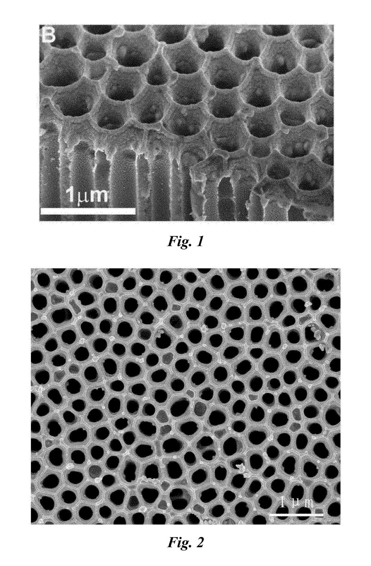
[0145]Step 1: Porous anodic alumina templates (hereafter abbreviated as NPT) were manufactured by a two-step anodic oxidation method. The method comprised the following steps: an aluminum foil was placed in 0.3 M phosphoric acid at 5° C. for the anodic oxidation; the oxidation voltage, starting from 50 V, was increased by 10 V in every 2 minutes, until it reached 150 V, and the voltage was kept for 24 hours, thereby to finish the first oxidation; thereafter, the alumina film formed in the first oxidation was removed by dissolving it, and under the same conditions as those of the first oxidation, the second oxidation was performed; after the second oxidation, the aluminum foil coated with a porous aluminum film was placed in a mixture liquid containing 1 M CuCl2 and 0.1 M HCl to remove the aluminum substrate by dissolution; at last, the porous aluminum film was transferred into 5 wt % H3PO4, to expand pores at 30° C. for about 1 h, thereby to produce the NPT of Example 1.

[0146]FIG. 1...

example 2

[0153](1) A NPT was produced by using the method in Example 1.

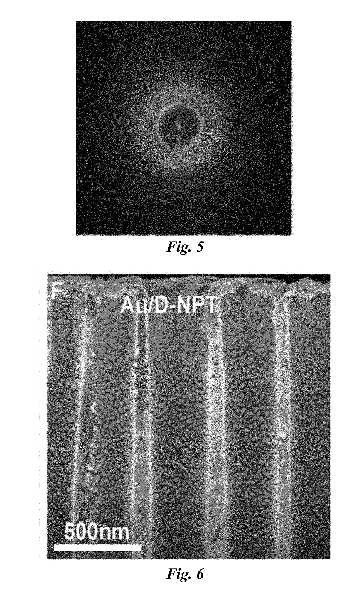
[0154](2) Gold (Au) is deposited both on the disordered surface of the NPT and on the inner walls of the pores on the disordered surface by using an ion beam film plating meter Gatan Model 682, in particular, the vacuum degree being 5×10⁻⁴ Pa, the electron gun voltage being 7 KeV, the electric current being 300 uA, and the depositing time being 16 min. The resultant product was the composite material device of Example 2 (hereafter abbreviated as Au / D-NPT).

[0155]Au / D-NPT comprised a NPT and gold particles adhered onto the inner walls of the pores of the NPT. The gold particles were disposed at a position from 0 to 2 μm in depth from the disordered surface of the NPT to the interior. Au / D-NPT further comprised a gold layer covered on the disordered surface of the NPT, and the gold layer only cover the regions without pores on the disordered surface. The thickness of the gold layer was from about 60 to 90 nm, and the thickne...

example 3

[0171]Step 1: A method for producing NPT having an average pore diameter of about 200 nm is described as follows:

[0172]Porous anodic alumina templates (hereafter abbreviated as NPT) was fabricated by a two-step anodic oxidation method. The method comprises the following steps: an aluminum foil was placed in 0.5 M phosphoric acid at 5° C. for anodic oxidation; the voltage of anodic oxidation started from 50 V, increased by 10 V in every 2 minutes, until it reached 150 V, and the voltage was kept for 24 hours, thereby to finish the first oxidation; thereafter, the alumina film formed in the first oxidation was dissolution removed, and under the same conditions as those of the first oxidation, the second oxidation was performed; after the second oxidation, the aluminum foil coated with a porous aluminum film was placed in a mixture liquid of 1 M CuCl2 and 0.1 M HCl to remove the aluminum substrate by dissolution; at last, the porous aluminum film was transferred into 5 wt % H3PO4, to e...


PUM

PropertyMeasurementUnit
Lengthaaaaaaaaaa
Fractionaaaaaaaaaa
Fractionaaaaaaaaaa

Abstract

The disclosed is provided with a composite material device, comprising a substrate, a plurality of pores provided on the substrate, and a plurality of metal particles adhered onto inner walls of the pores, the metal particles having a particle size of from 1 to 200 nm, wherein the plurality of metal particles have at least x different particle sizes d, x being larger than or equal to 2. The composite material device of the present discloser has a high light absorption rate and a broad light absorption wavelength range.

Description

TECHNICAL FIELD[0001]The disclosed relates to a composite Material field, and particularly to a composite material device.BACKGROUND ART[0002]Light absorbers are useful in a broad range of applications including light / thermal detection, solar energy conversion, and infrared imaging. The light absorbance of the light absorbers and the range of the absorption spectrum are essential factors for deciding the performances of the light absorbers. Ideal light absorbers have a high light absorbance rate in a broad wavelength range, and in other word, in the broad spectral range, the light absorbers have low light transmittance and low light reflectance.[0003]There are many light absorbers, particularly nano-plasmonic absorbers, in the related art. For example, there are light absorbers having a metal meta-surface structure and light absorbers having a cone structure. The spectra of light that can be absorbed by the light absorbers are broadened, owing to a composite resonance mode. A plasmo...

Claims


Application Information

Patent Timeline
IPC IPC(8): C02F1/14C23C14/46C23C14/30C25D11/04C23C14/18
CPCC02F1/14C23C14/46C23C14/30C25D11/045C23C14/185C02F2103/08C23C14/18C25D11/04Y10T428/26
Inventor ZHU, JIAZHOU, LINTAN, YINGLING
Owner NANJING UNIV
Why Eureka
Try Eureka