A method of fabricating a ceramic from a chemical reaction

a chemical reaction and ceramic technology, applied in the direction of engines, machines/engines, mechanical equipment, etc., can solve the problems of high cost of methods, difficult industrial production, and long fabrication duration of cmc parts

Active Publication Date: 2018-12-27
CENT NAT DE LA RECHERCHE SCI +1
View PDF0 Cites 2 Cited by
  • Summary
  • Abstract
  • Description
  • Claims
  • Application Information

AI Technical Summary

Benefits of technology

[0063]The coating as obtained in this way may form an environmental barrier serving for example to protect the part against oxidi

Problems solved by technology

This leads to fabrication durations for CMC parts that are long and makes the method expensive.
Nevertheless, preparing carbon xerogels can involve using substances classified as CMR (carcinogenic, mutagenic, or toxic for reproduction), which can make industrial production difficult.
The core of the material densifies poorly because of the premature closure of the pores at the periphery of the material.
Reactive species find it difficult to penetrate into the small pores and their concentration drops off very quickly going from the periphery to the core, thereby greatly slowing down and then preventing growth of the consolidation layer.
However feasibility has not been repor

Method used


Image

  • A method of fabricating a ceramic from a chemical reaction
  • A method of fabricating a ceramic from a chemical reaction
  • A method of fabricating a ceramic from a chemical reaction

Examples


example 1 (

Invention)

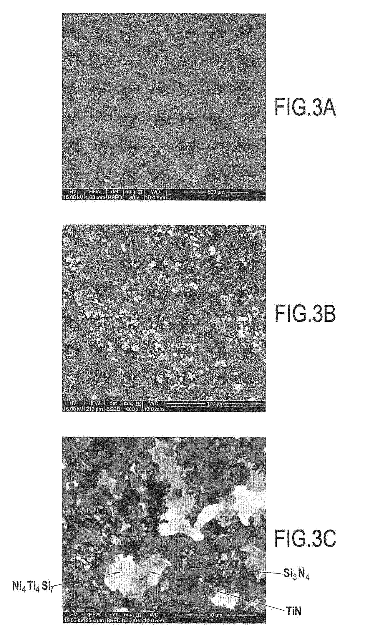
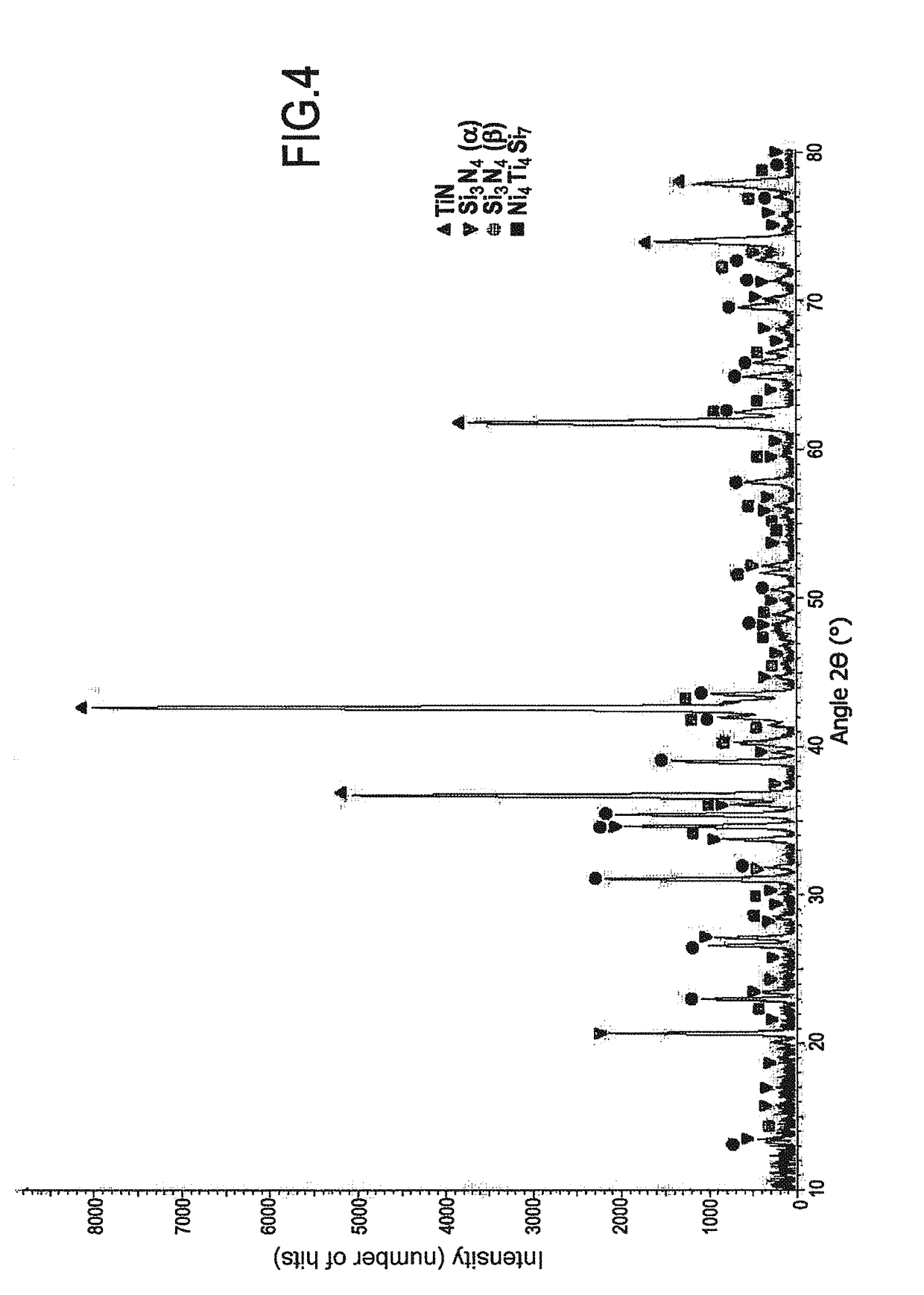
[0083]FIGS. 3A to 3C are photographs showing the material obtained after converting a sample having an initial composition of 90 at % TiSi2+10 at % Ni by treatment under normal pressure with N2 at 1100° C. for 40 hours (h). The phases present at the end of the treatment were TiN, Si3N4, and Ni4Ti4Si7 (see FIG. 4). It should be observed that at the end of the treatment, free silicon and residual TiSi2 were absent. This reaction was accompanied by an increase in volume of about 50%.

[0084]FIGS. 5B and 5C are photographs showing in particular a matrix obtained by converting an infiltrated powder (d50=300 nanometers (nm)) having an initial composition of 90 at % TiSi2+10 at % Ni treated under normal pressure with N2 at 1100° C. for 40 h within a fiber preform. The phases formed were identical to those described above (TiN, Si3N4, and Ni4Ti4Si7). No reaction was observable between the powder and the Nicalon® fibers coated in a PyC / SiC interphase.

[0085]Likewise, FIG. 5A also show...

example 4

[0105]Pellets of ZrSi2 were nitrided for 40 h under normal pressure of dinitrogen at a temperature of 1100° C.

[0106]When 10 at % of nickel were added to the mixture, and after 40 h of nitriding, the majority phases were ZrN and Si3N4. The presence of ZrSi2, ZrSi2Si, and NiZr was observed in the minority. The presence of free silicon was not observed.

[0107]Without adding nickel (not the invention), the majority phases were ZrN and ZrSi2 after 40 h of nitriding. Si3N4 was detected, but it constituted a minority phase. Free silicon was also detected.

[0108]Adding nickel thus facilitated nitriding of the metallic disilicide ZrSi2 even at a relatively low working temperature of 1100 C.°.

example 5

[0109]Pellets of ZrSi2 were nitrided for 40 h under normal pressure of dinitrogen at a temperature of 1100° C.

[0110]When a powder of AS13 alloy was added at 10 at %, and after 40 h of nitriding, the majority phases were ZrN, Si3N4, and ZrSi2. The presence of a minimum quantity of free silicon was observed.

[0111]Without adding the AS13 powder, and after 40 h of nitriding, the majority phases were ZrN and ZrSi2, with SiN, being observed in the minority. Free silicon was also detected.

[0112]Adding an aluminum alloy to the silicon thus facilitated nitriding the metallic disilicide ZrSi2 even at a relatively low working temperature of 1100° C.


PUM

PropertyMeasurementUnit
Temperatureaaaaaaaaaa
Fractionaaaaaaaaaa
Fractionaaaaaaaaaa

Abstract

A method of fabricating a ceramic material, the method including forming a ceramic material by performing a first chemical reaction at least between a first powder of an intermetallic compound and a reactive gas phase, a liquid phase being present around the grains of the first powder during the first chemical reaction, the liquid gas phase being obtained from a second powder of a metallic compound by melting the second powder or as a result of a second chemical reaction between at least one element of the first powder and at least one metallic element of the second powder, a working temperature being imposed during the formation of the ceramic material, which temperature is low enough to avoid melting the first powder.

Description

BACKGROUND OF THE INVENTION[0001]The invention relates to methods of fabricating ceramic materials and also to products that can be obtained by performing such methods.[0002]Chemical vapor infiltration (CVI) methods are known for densifying fiber preforms. Methods of that type consist in infiltrating a gas mixture containing all of the elements for forming the material within a porous preform in order to densify the preform. By way of example, that type of method is described in application FR 2 784 695. Chemical vapor infiltration is derived from the technique of chemical vapor deposition (CVD) and it possesses a deposition rate that is constant over time. It is a method that gives good properties to the material. Nevertheless, in order to obtain a ceramic matrix composite (CMC) that is uniform, while avoiding premature clogging at the periphery of the preform, it can be necessary to operate at low pressure and at relatively low temperature (≤1100° C.) in order to slow down growth ...

Claims


Application Information

Patent Timeline
IPC IPC(8): C04B35/58C04B35/591C04B35/622C04B35/645C04B35/80
CPCC04B35/58014C04B35/591C04B35/62222C04B35/645C04B35/806C04B2235/3891C04B2235/402C04B2235/405C04B2235/465C04B2235/5244C04B2235/5248C04B2235/614C04B2235/616C04B2235/80C04B35/5615C04B35/573C04B35/58007C04B35/58028C04B35/62842C04B35/62863C04B35/62868C04B35/62873C04B2235/46C04B2235/524C04B2235/5445C04B2235/5454C04B2235/72C04B2235/728F05D2300/6033F01D5/284F05D2300/177C04B35/80C04B35/515
Inventor MAILLE, LAURENCEROGER, JEROMELE PETITCORPS, YANNREIGNIER, BERNARD
Owner CENT NAT DE LA RECHERCHE SCI
Why Eureka
Try Eureka