Galvanically-Active In Situ Formed Particles for Controlled Rate Dissolving Tools

a technology which is applied in the field of in situ formed particles for controlled rate dissolving tools, can solve the problem that individual additive elements would not fully melt in molten magnesium, and achieve the effect of improving the surface hardness of said magnesium composi

Active Publication Date: 2019-02-14
TERVES
View PDF0 Cites 25 Cited by
  • Summary
  • Abstract
  • Description
  • Claims
  • Application Information

AI Technical Summary

Benefits of technology

[0097]In still another and/or alternative non-limiting aspect of the invention, there is provided a magnesium composite that includes in situ precipitation of galvanically-active intermetallic phases comprising a magnesium or a magnesium alloy and an additive constituting about 0.05-45 wt. % of said magnesium composite, said magnesium having a content in said magnesium composite that is greater than 50 wt. %, said additive forming metal composite particles or precipitant in said magnesium composite, said metal composite particles or precipitant forming said in situ precipitation of said galvanically-active intermetallic phases, said additive including one or more first additives having an electronegativity of 1.5 or greater. The magnesium composite can optionally further include one or more second additives having an electronegativity of 1.25 or less. The first additive can optionally have an electronegativity of greater than 1.8. The first additive can optionally include one or more metals selected from the group consisting of copper, nickel, cobalt, bismuth, silver, gold, lead, tin, antimony, indium, arsenic, mercury, and gallium. The first additive can optionally include one or more metals selected from the group consisting of copper, nickel, cobalt, bismuth, tin, antimony, indium, and gallium. The second additive can optionally include one or more metals selected from the group consisting of calcium, strontium, barium, potassium, sodium, lithium, cesium, and the rare earth metals such as yttrium, lanthanum, samarium, europium, gadolinium, terbium, dysprosium, holmium, and ytterbium. The magnesium alloy can optionally include over 50 wt. % magnesium and one or more metals selected from the group consisting of aluminum, boron, bismuth, zinc, zirconium, and manganese. The magnesium alloy can optionally include over 50 wt. % magnesi

Problems solved by technology
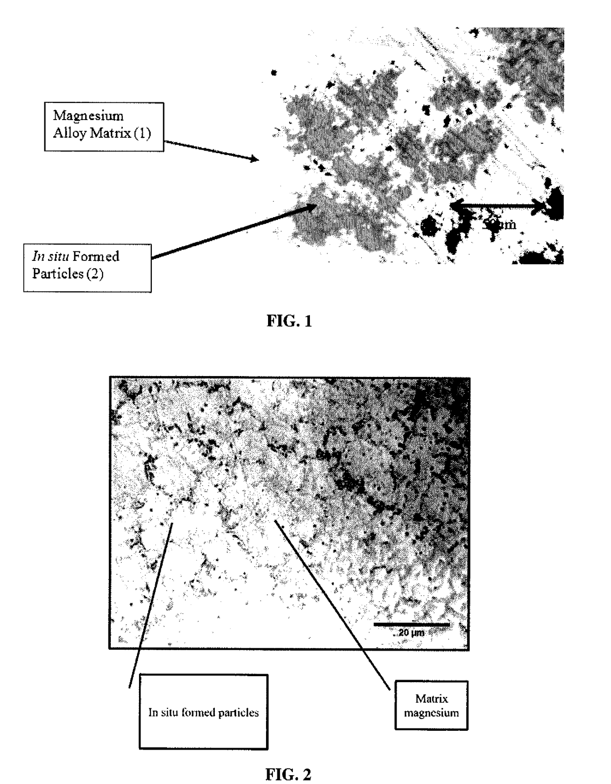
During the process of mixing the one or more additives in the molten magnesium or magnesium alloy, the one or more additives do not typically fully melt in the molten magnesium or magnesium alloy; however, the one or more additives can form a single-phase liquid with the magnesium while the mixture is in the molten state.
As such, th

Method used


Image

  • Galvanically-Active In Situ Formed Particles for Controlled Rate Dissolving Tools
  • Galvanically-Active In Situ Formed Particles for Controlled Rate Dissolving Tools
  • Galvanically-Active In Situ Formed Particles for Controlled Rate Dissolving Tools

Examples


example 1

[0138]An AZ91D magnesium alloy having 9 wt. % aluminum, 1 wt. % zinc and 90 wt. % magnesium was melted to above 800° C. and at least 200° C. below the melting point of nickel. About 7 wt. % of nickel was added to the melt and dispersed. The melt was cast into a steel mold. The cast material exhibited a tensile strength of about 14 ksi, an elongation of about 3%, and shear strength of 11 ksi. The cast material dissolved at a rate of about 75 mg / cm2-min in a 3% KCl solution at 90° C. The material dissolved at a rate of 1 mg / cm2-hr in a 3% KCl solution at 21° C. The material dissolved at a rate of 325 mg / cm2-hr. in a 3% KCl solution at 90° C.

example 2

[0139]The composite in Example 1 was subjected to extrusion with an 11:1 reduction area. The material exhibited a tensile yield strength of 45 ksi, an Ultimate tensile strength of 50 ksi and an elongation to failure of 8%. The material has a dissolve rate of 0.8 mg / cm2-min. in a 3% KCl solution at 20° C. The material dissolved at a rate of 100 mg / cm2-hr. in a 3% KCl solution at 90° C.

example 3

[0140]The alloy in Example 2 was subjected to an artificial T5 age treatment of 16 hours from 100-200° C. The alloy exhibited a tensile strength of 48 ksi and elongation to failure of 5% and a shear strength of 25 ksi. The material dissolved at a rate of 110 mg / cm2-hr. in 3% KCl solution at 90° C. and 1 mg / cm2-hr. in 3% KCl solution at 20° C.


PUM

PropertyMeasurementUnit
Temperatureaaaaaaaaaa

Abstract

A castable, moldable, and/or extrudable structure using a metallic primary alloy. One or more additives are added to the metallic primary alloy so that in situ galvanically-active reinforcement particles are formed in the melt or on cooling from the melt. The composite contains an optimal composition and morphology to achieve a specific galvanic corrosion rate in the entire composite. The in situ formed galvanically-active particles can be used to enhance mechanical properties of the composite, such as ductility and/or tensile strength. The final casting can also be enhanced by heat treatment, as well as deformation processing such as extrusion, forging, or rolling, to further improve the strength of the final composite over the as-cast material.

Description

[0001]The present invention is a continuation-in-part of U.S. patent application Ser. No. 15 / 641,439 filed Jul. 5, 2017, which in turn is a divisional of U.S. patent application Ser. No. 14 / 689,295 filed Apr. 17, 2015 (now U.S. Pat. No. 9,903,010 issued Feb. 27, 2018), which in turn claims priority on U.S. Provisional Patent Application Ser. No. 61 / 981,425 filed Apr. 18, 2014, which are incorporated herein by reference.FIELD OF THE INVENTION[0002]The present invention is directed to a novel magnesium composite for use as a dissolvable component in oil drilling. The invention is also directed to a novel material for use as a dissolvable structure in oil drilling. Specifically, the invention is directed to a ball or other structure in a well drilling or completion operation, such as a structure that is seated in a hydraulic operation, that can be dissolved away after use so that that no drilling or removal of the structure is necessary. Primarily, dissolution is measured as the time t...

Claims


Application Information

Patent Timeline
IPC IPC(8): C22F1/06C22C23/02C22C1/02
CPCC22C23/02C22F1/06C22C1/02C22C23/00
Inventor DOUD, BRIAN P.FARKAS, NICHOLAS J.SHERMAN, ANDREW J.
Owner TERVES
Why Eureka
Try Eureka