Image acquisition apparatus, spectral apparatus, methods, and storage medium for use with same

a technology of image acquisition and acquisition apparatus, applied in the field of spectroscope, can solve the problems of color image cannot be obtained, complex mechanisms, green resolution, etc., and achieve the effects of improving the resolution of acquired image, low cost, and high light utilization efficiency

Active Publication Date: 2019-05-30
CANON USA
View PDF7 Cites 6 Cited by
  • Summary
  • Abstract
  • Description
  • Claims
  • Application Information

AI Technical Summary

Benefits of technology

[0015]In color imaging for a SEE device, deterioration in resolution of green regions that determine resolution when images are formed is countered by obtaining data from pixels shifted as to each other with respect to wavelength, which may enable the effects of pixel shifting to be obtained, so resolution can be improved.
[0023]In accordance with at least another aspect of the present disclosure, the SEE technique(s) discussed herein may be employed to reduce the cost of at least one of manufacture and maintenance of SEE devices, systems and storage mediums by reducing or minimizing a number of optical components in an interference optical system, such as an interferometer.

Problems solved by technology

However, the technique described in U.S. Pat. No. 6,341,036 yields a monochrome image, and a color image cannot be obtained.
However, when the technique of U.S. Pat. No. 9,254,089 is used, three mechanisms that rotatively connect to the respective fibers become necessary, which makes the mechanisms complex.
While raising the resolution of green raises a final image resolution, the resolution of green, however, on the detector of the spectrometer is low or decreases, and, therefore, improving the resolution is difficult.
For example, since the unused wavelength region exists, the resolution of green on an image pickup element of a spectroscope decreases with the unused wavelength region, making improvement of the resolution difficult.

Method used


Image

  • Image acquisition apparatus, spectral apparatus, methods, and storage medium for use with same
  • Image acquisition apparatus, spectral apparatus, methods, and storage medium for use with same
  • Image acquisition apparatus, spectral apparatus, methods, and storage medium for use with same

Examples


first embodiment

[0075]Although at least the first embodiment illustrates signal spectral sequences being imaged on the imaging devices by a single imaging lens, this is not restrictive. For example, a dichroic mirror may be inserted between the collimator lens (e.g., the collimator lens 401) and diffractive grating (e.g., the diffractive grating 402) or element to split into the respective wavelength bands, and have imaging lenses prepared for each split wavelength band. This enables the resolution to be improved for each wavelength band, and providing multiple imaging devices for each imaging lens can further improve resolution. Thus, branching into multiple light fluxes from detection fibers in a SEE spectroscope, forming multiple spectral sequences, and performing detection at multiple imaging devices used for detection by pixel shifting, enables the image resolution of the SEE to be improved.

[0076]At least a second embodiment of the present disclosure will be described with reference to FIG. 8....

fourth embodiment

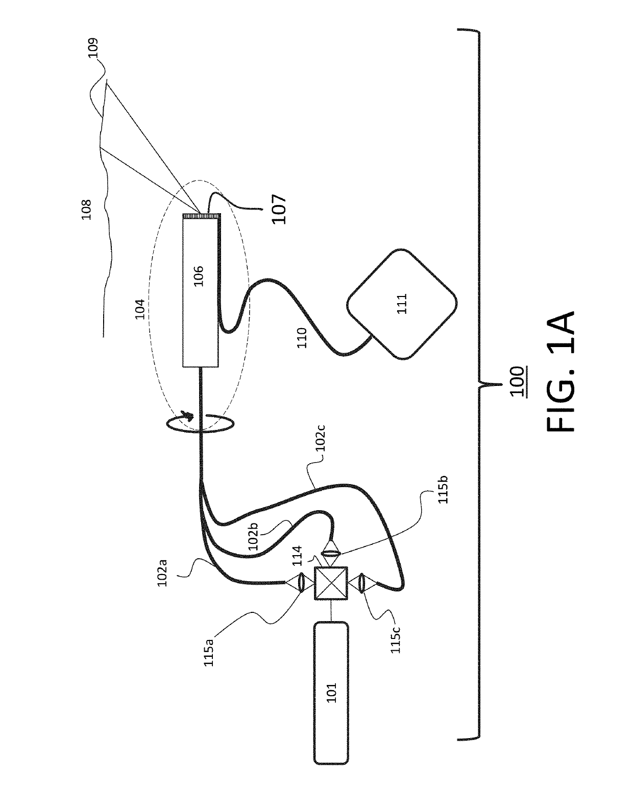
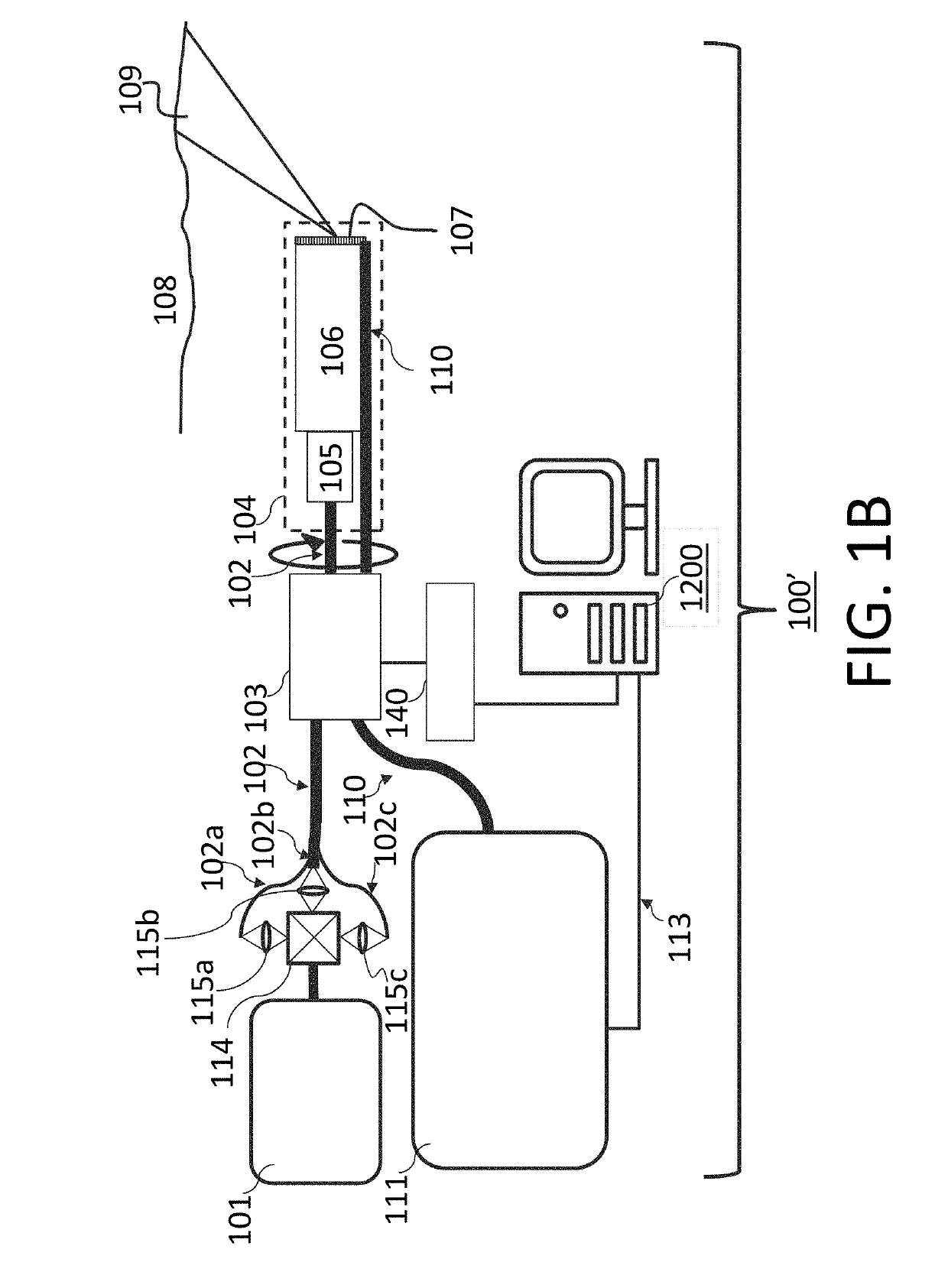
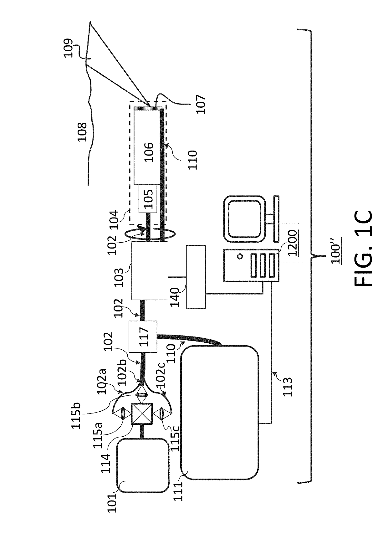
[0110]The light irradiation or probe unit 104 is inserted into a sheath 301 that is transparent with regard to the measurement wavelength bands, and the light irradiation or probe unit 104 rotates within the sheath 301 (the sheath portion does not rotate). Thus, the light irradiation or probe unit 104 can be inserted into the body cavity, and two-dimensional images within the body cavity can be obtained by the method described in at least the

[0111]The light irradiation or probe unit 104 from the RJ 103 toward the distal end, and the sheath 301, can be removed and exchanged. The light irradiation or probe unit 104 and sheath 301 that have been inserted into the body can be removed and discarded, and a new light irradiation or probe unit 104 attached, to eliminate the cleaning process.

[0112]This endoscope is configured using optical fiber for illumination and optical fiber for detection, and accordingly it is at least one feature thereof that an endoscope that is extremely slender, ar...

seventh embodiment

[0115]Referring to FIGS. 22 to 28B, the present disclosure is described herein. FIG. 22 illustrates an entirety of an SEE system including a spectroscope according to the present embodiment, and FIG. 23 illustrates an optical cross-section of the spectroscope installed inside the SEE system. FIGS. 24A and 24B illustrate a state in which white illumination light is formed with a diffraction element, FIG. 25 illustrates the diffraction efficiency of the diffraction element of a probe portion, and FIG. 26 illustrates an example of wavelength characteristics of dichroic mirrors installed inside the spectroscope. FIGS. 27A to 27C are diagrams illustrating an arrangement of a spectral sequence spectrally dispersed on an image pickup element with a diffraction grating, and FIGS. 28A and 28B are diagrams illustrating an incident angle characteristic of the diffraction grating.

[0116]In at least the embodiment of FIG. 22, light emitted from a white light source 101 is transmitted through an i...


PUM


Abstract

Image acquisition apparatuses, spectral apparatuses, methods and storage mediums for use with same are provided herein. At least one apparatus includes: a diffraction element irradiated by a light; a fiber for receiving reflected scattered light from a subject; a diffraction grating dispersing the transmitted light into light fluxes of wavelength bands again; an optical system imaging the split light fluxes; and an imaging device near the focal point of the optical system. An image is changed by rotating the diffraction grating, from which a two-dimensional image is acquired. The transmitted light may be branched into two or more, and input to a collimator lens and imaged as multiple spectral sequences by the optical system. At least one apparatus may form light fluxes traveling at different angles; and may acquire spectral information of the reflected and scattered light. Preferably, for the luminous fluxes, no gap exists in an image.

Description

BACKGROUND OF THE INVENTIONField of the Invention[0001]The present invention relates to one or more embodiments of an image acquisition apparatus, such as an endoscope, and a spectral apparatus, and more particularly relates to a spectroscope that splits and measures obtained light fluxes according to wavelengths, such as, but not limited to, spectrally encoded endoscopy (SEE) apparatuses and systems, and methods and storage mediums for use with same. Examples of SEE applications include imaging, evaluating and characterizing / identifying biological objects or tissue, such as, but not limited to, for gastro-intestinal, cardio and / or ophthalmic applications.Description of the Related Art[0002]There have been known endoscope apparatuses used for intraluminal measurement. Endoscopes enable real-time observation of intraluminal information. The smaller the outer diameter is, the wider the variety of lumina into which the endoscope can be inserted is, which may increase the observation ar...

Claims


Application Information

Patent Timeline
Patent Type & Authority Applications(United States)
IPC IPC(8): G02B27/10F21K9/64F21V8/00G01J3/28G01J3/02G01J3/04G01J3/50
CPCG02B27/1013F21K9/64G02B6/0068G01J3/2823G01J3/024G01J3/04G01J3/502A61B5/0075G01J3/18G01J3/36G01J3/0208G01J3/0218G02B6/34G02B6/3624G02B6/4215G02B6/4298A61B5/6852A61B5/42G02B23/2469G02B27/4227G02B23/2407G02B27/4244
Inventor KOYAMA, OSAMUYAMAMOTO, AKIRAKOHARA, NAOKI
Owner CANON USA
Why Eureka
Try Eureka