
Network interconnect as a switch

a network interconnection and switch technology, applied in the field of computer networks, can solve the problems of high hardware requirements, high cost of data switching equipment, and high error-prone communication channels, and achieve the effects of reducing hardware requirements, short built time, and simplifying the data center network infrastructur

Active Publication Date: 2019-08-08
WONG DAVID I KEONG
View PDF3 Cites 32 Cited by
  • Summary
  • Abstract
  • Description
  • Claims
  • Application Information

AI Technical Summary

Benefits of technology

This patent aims to simplify the infrastructure of data centers to reduce power consumption and cooling requirements. The invention also aims to address issues such as space usage, hardware cost, network performance, management, and the need for a quick build time. Overall, the invention reduces the need for expensive hardware and helps manage network performance more efficiently.

Problems solved by technology

A basic concept in data communication is that communication channels can be error prone.
Transmission over such communication channels at higher data rates and over large distances requires complex and costly transceivers.
In today's communication networks, data is typically aggregated before transmitting on to “uplink” to connect to external network (e.g., the Internet), which tends to be the most expensive port of the data switching equipment.
The aggregation model is not necessarily the only—or the most suitable—solution in a data center.
In the multi-rooted tree, the shortest single-path routing protocol can significantly underutilize the available bandwidths.
Equal cost multi-path routing can be used in conjunction with most routing protocols, because it is a per-hop decision limited to a single router.
Non-uniform communication patterns, especially those involving transfers of large blocks of data, do not perform well under ECMP without careful scheduling of flows to avoid network bottlenecks.
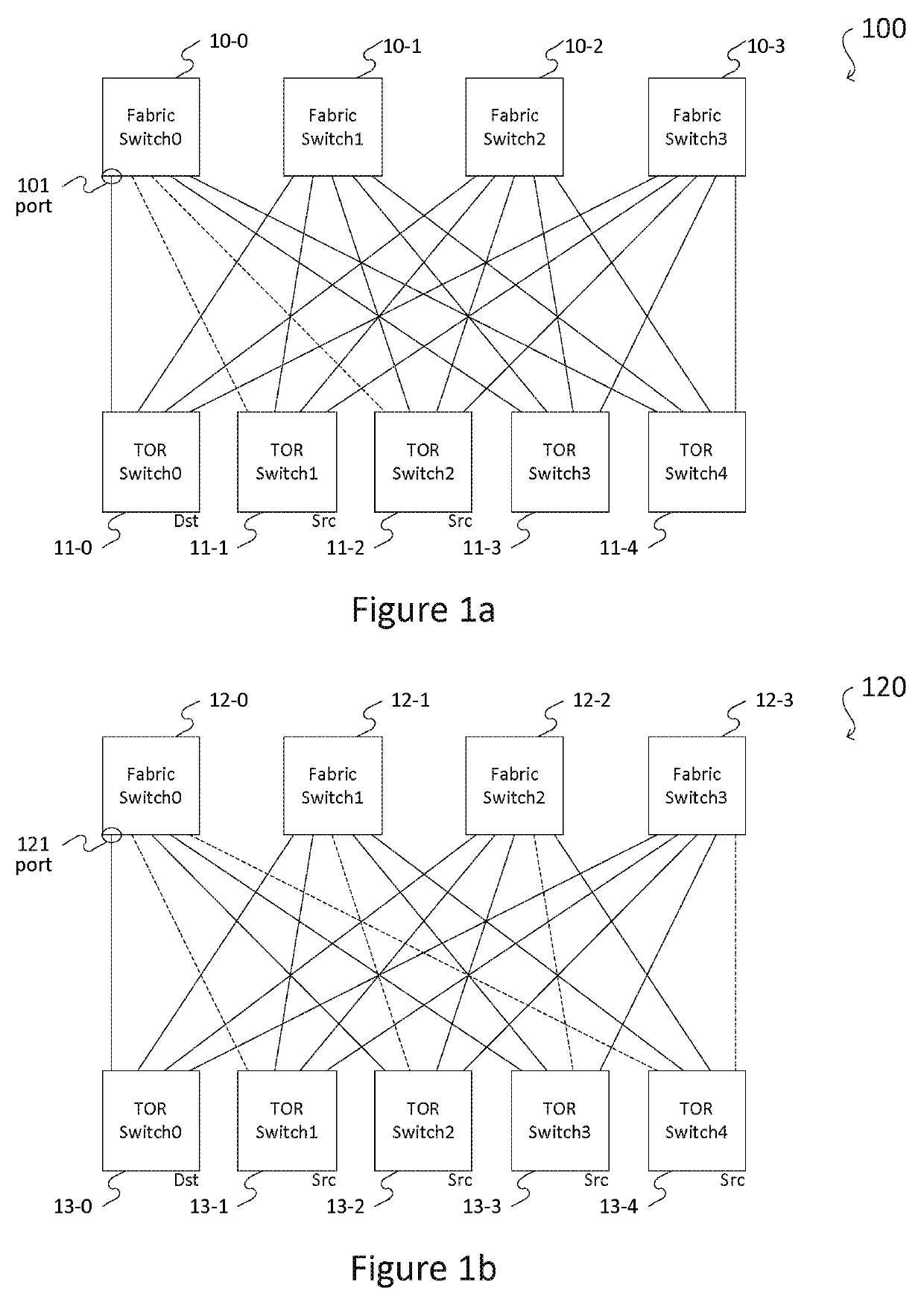
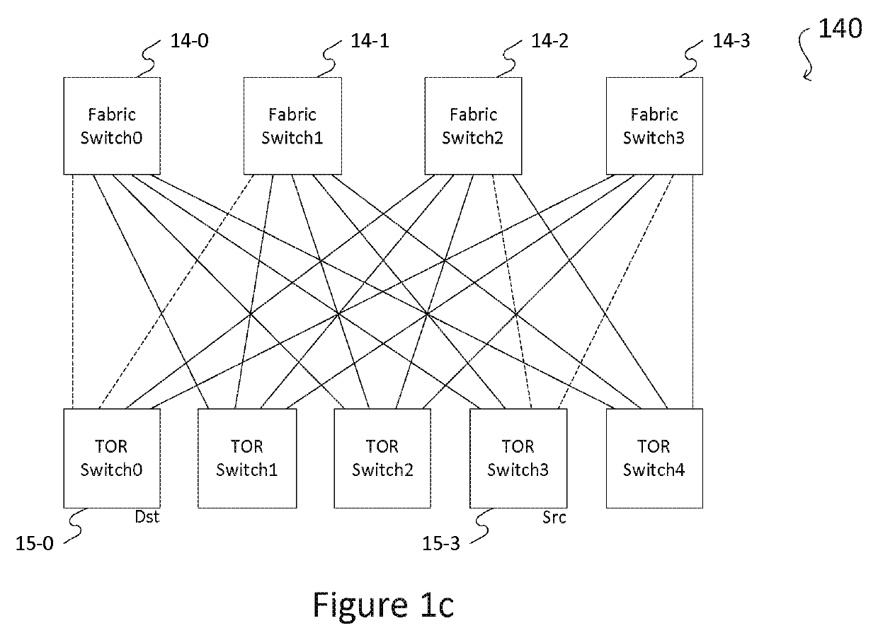
A fat tree network suffers from three types of drawbacks—i.e., 1) congestion due to hash collision, 2) congestion due to an aggregation model, and 3) congestion due to a blocking condition.
However, by chance, each flow is hashed to a path that goes through fabric switch 10-0, which causes congestion at designating port 101 of fabric switch 10-0.
Furthermore, the static mapping of the flows to paths by hashing does not consider either current network utilization or the sizes of the flows, so that the resulting collision overwhelms switch buffers, degrade overall switch utilization, and increases transmission latency.
Second, in a fat tree network, the total bandwidth of the aggregated traffic may exceed the bandwidth of all the downlinks of all the fabric switches facing the same TOR switch, resulting in aggregation congestion, as shown in FIG. 1b.
Such aggregation congestion is a common problem in the aggregation model of today's switching network, and requires detailed rate limiting to avoid congestion.
Overall, multiplexing the blocked flow on to the existing flows results in increased congestion, latency and / or packet loss.
The cost of lithographic and heat density will ultimately limit how many transistors can be packed into a single silicon package.
The primary obstacle that hinders high-speed operation on PCB is the frequency-dependent losses of the copper-based interconnection due to skin effects, dielectric losses, channel reflections, and crosstalk.
Copper-based interconnection faces the challenge of bandwidth limit as the data rate exceeds several tens of gigabit per second (Gb / s).
These limitations affect data center networks by, for example, increasing power consumption, slowing of performance increase, and increasing procurement cycle.
However, do not expect a very high-radix chip, which would allow network scalability, to emerge any time soon.2 One must think beyond the aggregation model (e.g., the disaggregation model) to meet new network challenges.
Such routing protocols increase the burden on the developer and create a tight coupling between applications and the network.
Data center networks of this type thus have a much looser coupling between applications and network topology, placing the burden of path selection on the network switches themselves.
However, there are strict requirements and restrictions on the network topology.
Data center technology based purely on Internet BGP routing cannot effectively support multipath with non-shortest path topologies.
However, even now direct network topologies (e.g., Dragonfly, HyperX, Slim Fly, BCube, and Flattened Butterfly), which employ paths of different lengths, have not seen adoption in data centers because of the limitations imposed by both commodity data center switches and the widespread adoption of ECMP routing in data center networks.
ECMP is wasteful of network capacity when there is localized congestion or hot-spots, as it ignores uncongested longer paths.
Further, even in hierarchical networks, ECMP makes it hard to route efficiently in the presence of failures, and when the network is no longer completely symmetric, and non-shortest paths are available for improving network utilization.
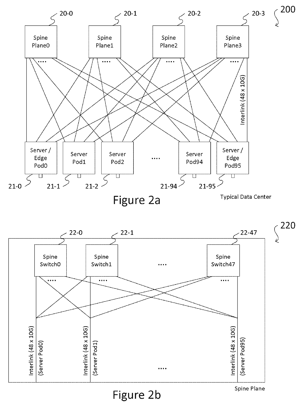
The implementation of FIG. 2a provides in practice improved congestion performance but does not eliminate congestion.

Method used


Image

  • Network interconnect as a switch
  • Network interconnect as a switch
  • Network interconnect as a switch

Examples


Embodiment Construction

[0072]The present invention simplifies the network architecture by eliminating the switches in the fabric layer based on a new fabric topology, referred herein as the “interconnect-as-a-switch” (ICAS) topology. The ICAS topology of the present invention is based on the “full mesh” topology. In a full mesh topology, each node is connected to all other nodes. The example of a 9-node full mesh topology is illustrated in FIG. 3. The inherent connectivity of a full mesh network can be exploited to provide fabric layer switching.

[0073]As discussed in further detail below, the ICAS topology enables a data center network that is far superior to a network of the fat tree topology used in prior art data center networks. Unlike other network topologies, the ICAS topology imposes a structure on the network which reduces congestion in a large extent. According to one embodiment, the present invention provides an ICAS module as a component for interconnecting communicating devices. FIG. 4a shows ...


PUM


Abstract

An interconnect as a switch module (“ICAS” module) comprising n port groups, each port group comprising n−1 interfaces, and an interconnecting network implementing a full mesh topology where each port group comprising a plurality of interfaces each connects an interface of one of the other port groups, respectively. The ICAS module may be optically or electrically implemented. According to the embodiments, the ICAS module may be used to construct a stackable switching device and a multi-unit switching device, to replace a data center fabric switch, and to build a new, high-efficient, and cost-effective data center.

Description

CROSS-REFERENCE TO RELATED APPLICATION[0001]This application is a Continuation-in-Part application of U.S. application Ser. No. 15 / 888,516 filed Feb. 5, 2018, which is incorporated herein by reference in their entireties, including any figures, tables, and drawings.FIELD OF INVENTION[0002]The present invention relates to computer network. In particular, the present invention relates to interconnecting structure of ICAS module, stackable switching device, multi-unit chassis switching device, network pod, fanout cable transpose rack and datacenter network.DISCUSSION OF THE RELATED ART[0003]As a result of the recent rapid growth in application needs—in both size and complexity—today's network infrastructure is scaling and evolving at a high rate. The data traffic that flows from a data center to the Internet—i.e., “machine-to-user” traffic—is large, and ever increasing, as more people get connected, and as new products and services are created. However, machine-to-user traffic is merel...

Claims


Application Information

Patent Timeline
Patent Type & Authority Applications(United States)
IPC IPC(8): H04L12/24H04Q11/00H04L12/733H04L12/44H04L12/803H04L45/122H04L49/111
CPCH04L41/12H04Q11/0071H04L45/122H04L12/44H04L41/0826H04L47/125H04Q2011/0098H04Q2011/0096H04L49/15H04L49/1515H04Q11/0005H04Q2011/0052H04B10/25H04B10/40H04L12/4625H04Q11/0003H04Q11/0062H04Q2011/006H04L49/1507
Inventor WONG, DAVID I-KEONG
Owner WONG DAVID I KEONG
Learn More