
Method and Apparatus for Gas Destruction

a technology of gas destruction and gas cylinder, which is applied in the direction of lighting and heating equipment, combustion types, separation processes, etc., to achieve the effect of speeding up the degassing process

Active Publication Date: 2019-11-28
MEBROM RES & DEV PTY LTD
View PDF0 Cites 3 Cited by
  • Summary
  • Abstract
  • Description
  • Claims
  • Application Information

AI Technical Summary

Benefits of technology

The patent describes a process for preventing damage to an engine by using a load bank to increase the fuel / air mixture and raise combustion temperatures. The load can be an electrical, pneumatic or hydraulic load. Additionally, ultrasonic equipment can be used to speed up the process of de-acidifying the engine by driving dissolved carbon dioxide gas out of the solution, reducing corrosion and damage to the engine.

Problems solved by technology

However, at one time it was estimated that up to 80% of the methyl bromide applied for these uses was being emitted into the air, and by the early 1990's methyl bromide was recognised to be a significant contributor to stratospheric ozone depletion.

Method used


Image

  • Method and Apparatus for Gas Destruction

Examples


Embodiment Construction

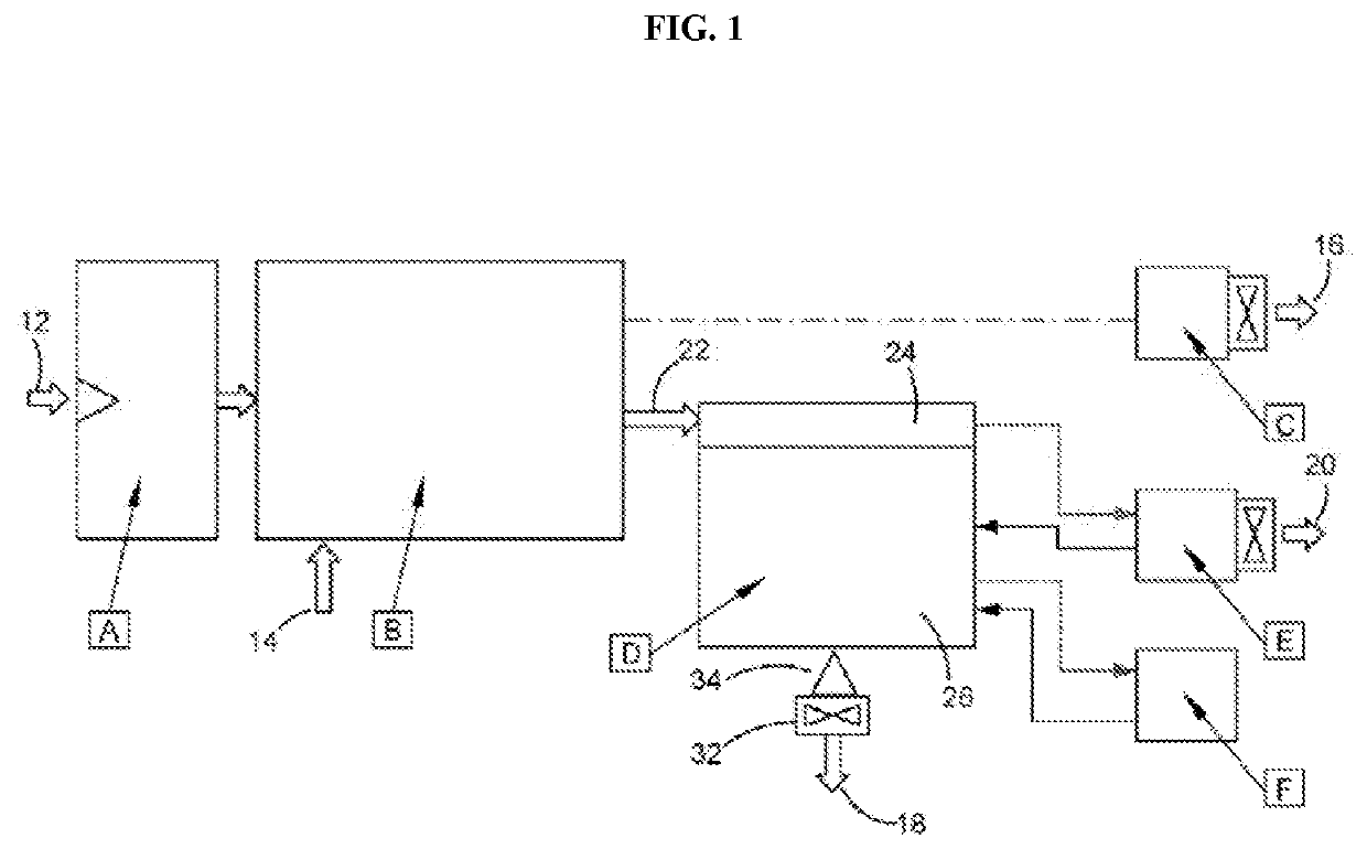
[0046]Illustrated in FIG. 1 is a schematic flow diagram showing a preferred embodiment of a target gas destruction method and apparatus, referred to hereafter as a Gas Destruction Unit (GDU) in accordance with the present invention. The central functions are identified broadly as follows:[0047]Box A—target gas inlet 12, with target gas filtering[0048]Box B—atmospheric air inlet 14, air filtering, target gas and air mixing, forced induction diesel engine[0049]Box C—load bank, with useful heat outlet 16[0050]Box D—scrubber system, with vent gas outlet 18 to atmosphere[0051]Box E—optional cooling, with useful heat outlet 20[0052]Box F—optional desalination

[0053]Referring now to each of these central functions in turn, in Box A there is provided a filter assembly where target gas from, for example a fumigation chamber, enters the GDU via a flexible tube inlet 12, in this embodiment containing high volume removable filter elements to trap solids and excessive moisture.

[0054]Located in Bo...


PUM

PropertyMeasurementUnit
concentrationaaaaaaaaaa

Abstract

A method for the destruction of a target gas, the method including: a) compressing at a first pressure a mixture of air and target gas to produce a compressed target gas mixture; b) destroying the target gas by combusting the compressed target gas mixture with diesel fuel in a forced-induction internal combustion engine, at a combustion pressure greater than the first pressure in the turbocharger, to produce an oxidised exhaust gas, the combustion occurring while maintaining a load on the diesel engine with a load bank; and c) processing the oxidised exhaust gas to produce a vent gas for venting to atmosphere where the vent gas includes substantially no target gas.

Description

TECHNICAL FIELD OF INVENTION[0001]The present invention relates to the destruction of harmful or undesirable gases, which might otherwise be vented to atmosphere, these gases being referred to as “target” gases. A particular example of a target gas is a fumigant that has been used to fumigate freight containers and railcars (or other buildings and structures that might require fumigation), such as methyl bromide, sulfuryl fluoride and phosphine.[0002]In this respect, the development of the present invention has arisen from work into the destruction of the target gas methyl bromide, therefore much of the following description will only refer to methyl bromide as the target gas for destruction. However, the invention is not to be so limited.BACKGROUND OF INVENTION[0003]Methyl bromide (CH3Br, also known as bromomethane) has been used very successfully as a pesticide and fumigant for many years. However, at one time it was estimated that up to 80% of the methyl bromide applied for these...

Claims


Application Information

Patent Timeline
Patent Type & Authority Applications(United States)
IPC IPC(8): F23G7/06F02D19/06F23G5/12F01N3/08B01D53/14
CPCF23G5/12F23G7/065B01D2252/103F02D19/0642B01D53/1493F01N3/08F23G2209/14B01D53/34B01D2251/11B01D2257/204B01D2257/2062B01D2257/30B01D2257/553
Inventor BARTOLO, KEVIN R.
Owner MEBROM RES & DEV PTY LTD
Learn More