
Methods and System for Multi-channel Bio-optical Sensing

a bio-optical sensing and multi-channel technology, applied in the field of optical monitoring of characteristic of an organism, can solve the problems of low signal-to-noise ratio (snr), motion artifacts, and wearable ppg sensors that are far from exhibiting performance characteristics that would allow them to become reliable for mobile applications, so as to reduce background noise, reduce non-pulsatile background noise, and increase optical power

Active Publication Date: 2019-12-26
MASSACHUSETTS INST OF TECH
View PDF10 Cites 7 Cited by
  • Summary
  • Abstract
  • Description
  • Claims
  • Application Information

AI Technical Summary

Benefits of technology

The optical sensing system described in this patent allows for more accurate and reliable sensing of biological samples. It can recognize and distinguish target blood vessels from other tissues and can manage its power to enhance sensitivity and accuracy. It can also combine or analyze data from multiple channels to improve measurement accuracy. Additionally, the system can fuse data from different optical channels to provide a more reliable readout of certain types of tissue. This approach is not possible with conventional PPG approaches. Overall, the optical sensing system provides a more efficient and effective tool for biological sensing and analysis.

Problems solved by technology

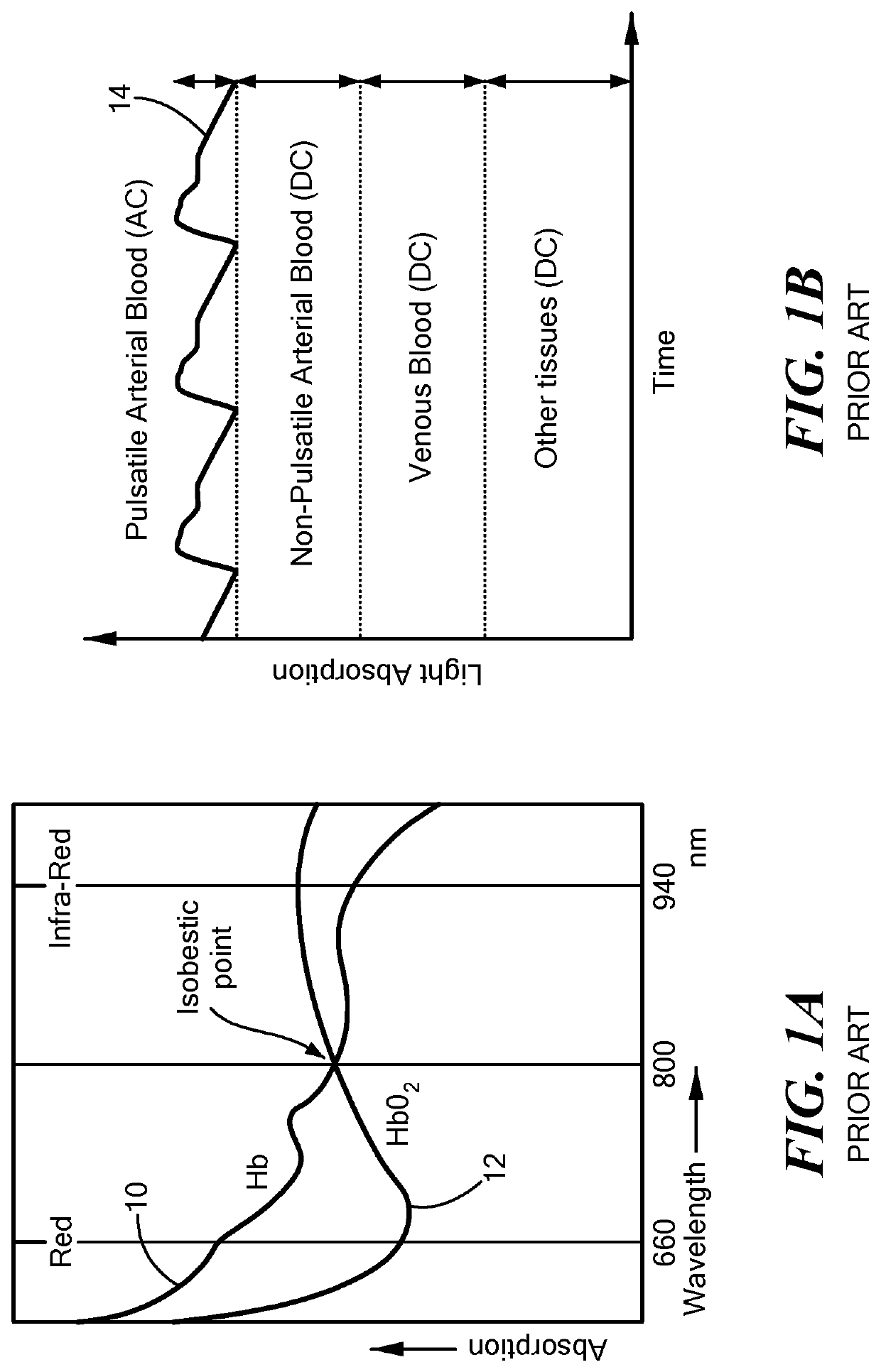
However, wearable PPG sensors (e.g., commercial heart rate monitors) are far from exhibiting performance characteristics that would allow them to become reliable for mobile applications.
They are prone to motion artifacts, low signal-to-noise ratio (SNR), and undesirable form factor, probing site restrictions, and excessive power consumption.
Several major limitations hinder the wide application of wearable PPG sensing:
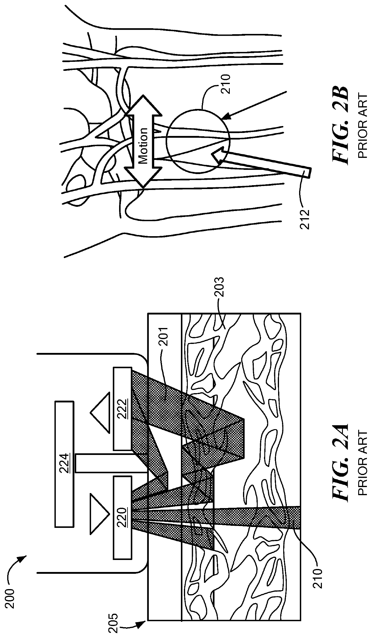
Divergence of LED light beam 210 causes further optical power loss.
Any further variance of background conditions (e.g., ambient light illumination, motion artifacts, venous pulsation artifact due to high-skin pressure-induced venous congestion) further degrades the already low SNR and makes the readout unreliable.
However, due to the fundamentally same sensing principle as that of the “single-pixel” detection architecture, such techniques provide limited improvement on SNR at the expense of significantly increased optical power consumption.
Such deviations usually lead to erroneous readouts and frequently happen in mobile usages, which is a leading issue for state-of-the-art wearable PPG sensors and heart monitors.
Although attempts had been made to mitigate these issues using advanced signal processing and motion sensors 224 (e.g., accelerometers), the improvement is not sufficient for mobile implementations, fundamentally limited by the physical “single pixel” LED-PD sensing architecture.
Such undesired light exposure may overwhelm the PPG signal or saturate the PD 222, resulting in corrupted signal readouts.
For measurements that require contact between the sensor 200 and skin 205, high skin pressure may cause venous congestion that leads to venous pulsation artifacts.
Since the venous blood typically possesses lower HbO2 concentration than the arterial blood, such artifacts introduce inaccuracies into the measurement results.
However, the probing sites are limited to such regions with limited blood perfusion, which are more susceptible to environmental extremes, such as low ambient temperatures (possible operation conditions for military personnel or athletes in training).
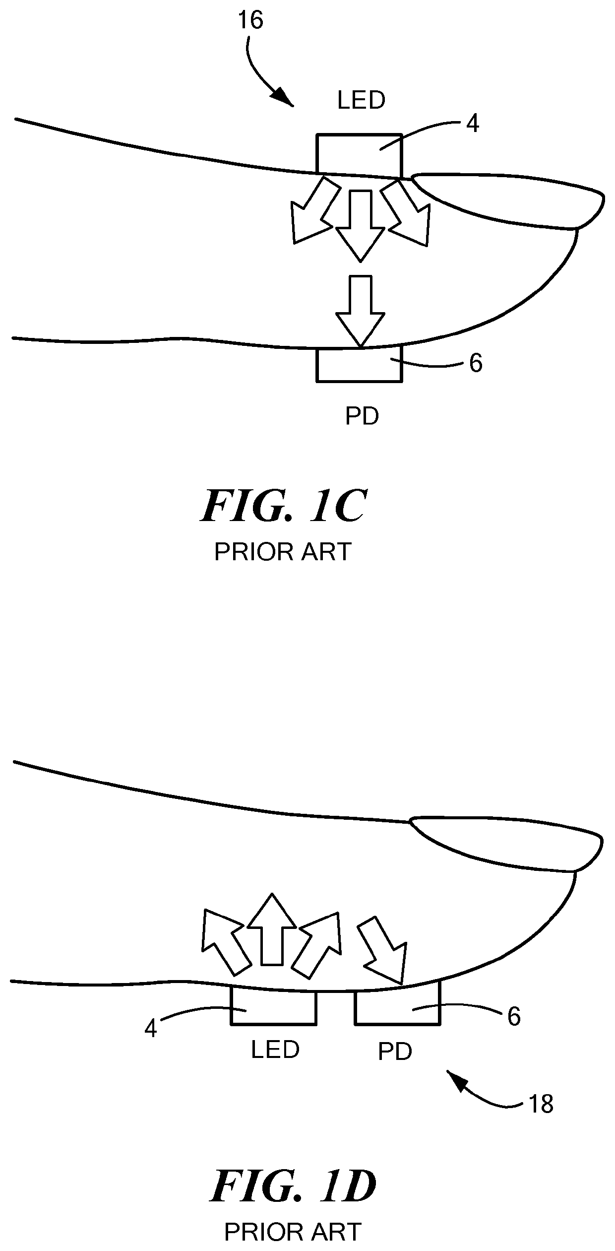
Another obvious disadvantage of the fingertip sensor is its interference with daily activities if utilized for continuous measurements.
However, due to the more complex optical path, their sensing accuracy is more susceptible to external factors, such as motion artifacts and ambient illumination.
In addition, due to the complexity of other vessels and tissues under the skin, each type of pulse oximeter is only suitable for a specified application site.
Inappropriate device deployment usually leads to erroneous readings.
As a result, a vast amount of optical power is wasted to generate signals that only contribute to background noise which further degrades SNR.
In addition, the necessity to include a 3D accelerometer in commercial heart-rate monitors further contribute to the overall power budget of such wearable devices with limited performance improvement.
The array sensor module of Lee is necessarily limited to a small number of sensors.

Method used


Image

  • Methods and System for Multi-channel Bio-optical Sensing
  • Methods and System for Multi-channel Bio-optical Sensing
  • Methods and System for Multi-channel Bio-optical Sensing

Examples


Embodiment Construction

[0023]In accordance with embodiments of the invention, a novel ultra-compact bio-optical sensing platform is described. Embodied as a wearable PPG pulse oximeter, it is designed to measure blood oxygen saturation (SpO2), heart rate (HR), and respiration in intense motions with high reliability through differential optical probing of a variety of vascular elements, such as blood vessels positioned at different depth under the skin, e.g., arteries (>2 mm in depth) and capillaries (˜200 μm in depth). The optical sensing platform may also serve as a planar integrated speckle imaging system for measuring blood flow properties. The optical sensing system consists of a light source (micro-LEDs, lasers, for example) and PD arrays linked by micro-optic-coupled optical probing and detection channel arrays. A novel method is also described that is based on the multi-channel bio-optical sensing approach for biological tissue detection, identification, sensing, and tracking.

[0024]According to on...


PUM


Abstract

A sensor, such as a photoplethysmography sensor, for non-invasively monitoring a characteristic of an organism, such as a vital body sign. The sensor has multiple light sources disposed on a substrate and an array of optical probing channels for conveying light from the light sources to a probed region. Each detector pixel of an array of detector pixels receives light from a respective optical detection channel after interaction with a subregion of the probed region and spatial filtering, and generates a corresponding pixel signal. A processor derives a value of the vital body sign based at least upon the plurality of pixel signals

Description

[0001]The present application claims the priority of U.S. Provisional Application No. 62 / 458,318, filed Feb. 13, 2017, which is hereby incorporated by reference.TECHNICAL FIELD[0002]The present invention relates to the optical monitoring of characteristic of an organism, such as a vital body sign, and, more particularly, to photoplethysmographs and speckle imaging incorporating arrays of optical channels that collectively guide light to a plurality of loci within a biological tissue of interest.BACKGROUND ART[0003]By sensing the interaction between light and blood vessels, photoplethysmographic (PPG) measurements allow non-invasive optical monitoring of vital body signs such as blood oxygen saturation, heart rate, blood flow rate, etc. PPG sensors have been widely used in clinical cardiovascular monitoring systems, such as pulse oximeters, respiration monitors, blood flowmeters, cardiac output monitors, blood pressure systems, detection of cardiac arrhythmia, sleep disorder monitors...

Claims


Application Information

Patent Timeline
IPC IPC(8): A61B5/00
CPCA61B5/0816A61B5/02416A61B5/0059A61B5/14551A61B2562/043A61B2562/0238A61B5/7214A61B5/02427A61B5/02438A61B5/0261A61B5/1075A61B5/1079A61B5/14552A61B5/489A61B5/6824A61B5/6826A61B2562/046
Inventor HU, JUEJUNGU, TIAN
Owner MASSACHUSETTS INST OF TECH
Learn More