Multijunction photovoltaic device

a photovoltaic device and multi-junction technology, applied in the direction of photovoltaic energy generation, semiconductor devices, electrical equipment, etc., can solve the problems of high material cost, high manufacturing cost of solar energy capture devices, and historically impeded its widespread use, so as to achieve sufficient transversal conductivity and reduce reflection losses

Active Publication Date: 2020-02-20
OXFORD PHOTOVOLTAICS
View PDF0 Cites 9 Cited by
  • Summary
  • Abstract
  • Description
  • Claims
  • Application Information

AI Technical Summary

Benefits of technology

[0016]To reduce the detrimental influence of local shunt paths, the present inventors have developed a monolithically integrated perovskite-on-silicon multi-junction photovoltaic device that comprises an interconnect layer, disposed between the perovskite sub-cell and the silicon sub-cell, which has a very low lateral conduct

Problems solved by technology

To this end, solar energy is seen as one of the most promising technologies, nevertheless, the high cost of manufacturing devices that capture solar energy, including high material costs, has historically hindered its widespread use.
If the band gap is too high, most daylight photons cannot be absorbed; if it is too low, then most photons have much more energy than necessary to excite electrons across the band gap, and the rest will be wasted.
In comparison, equivalent single-anion perovskites are relatively unstable, with bleaching occurring quickly when fabricating films from the single halide perovskites in ambient conditions.
Whilst a mechanically stacked multi-junction photovoltaic device does not require current matching between the sub-cells, the additional size and cost of the additional contacts and substrates, and a lower practical efficiency limit, make mechanically stacked structures less favourable than monolithically integrated structures.
Firstly, the high lateral conductivity of the ITO layer (specific conductivity >2×10² S/cm) makes potent

Method used


Image

  • Multijunction photovoltaic device
  • Multijunction photovoltaic device
  • Multijunction photovoltaic device

Examples


Embodiment Construction

Definitions

[0049]The term “matrix”, as used herein, refers to a fine-grained material in which larger objects are embedded.

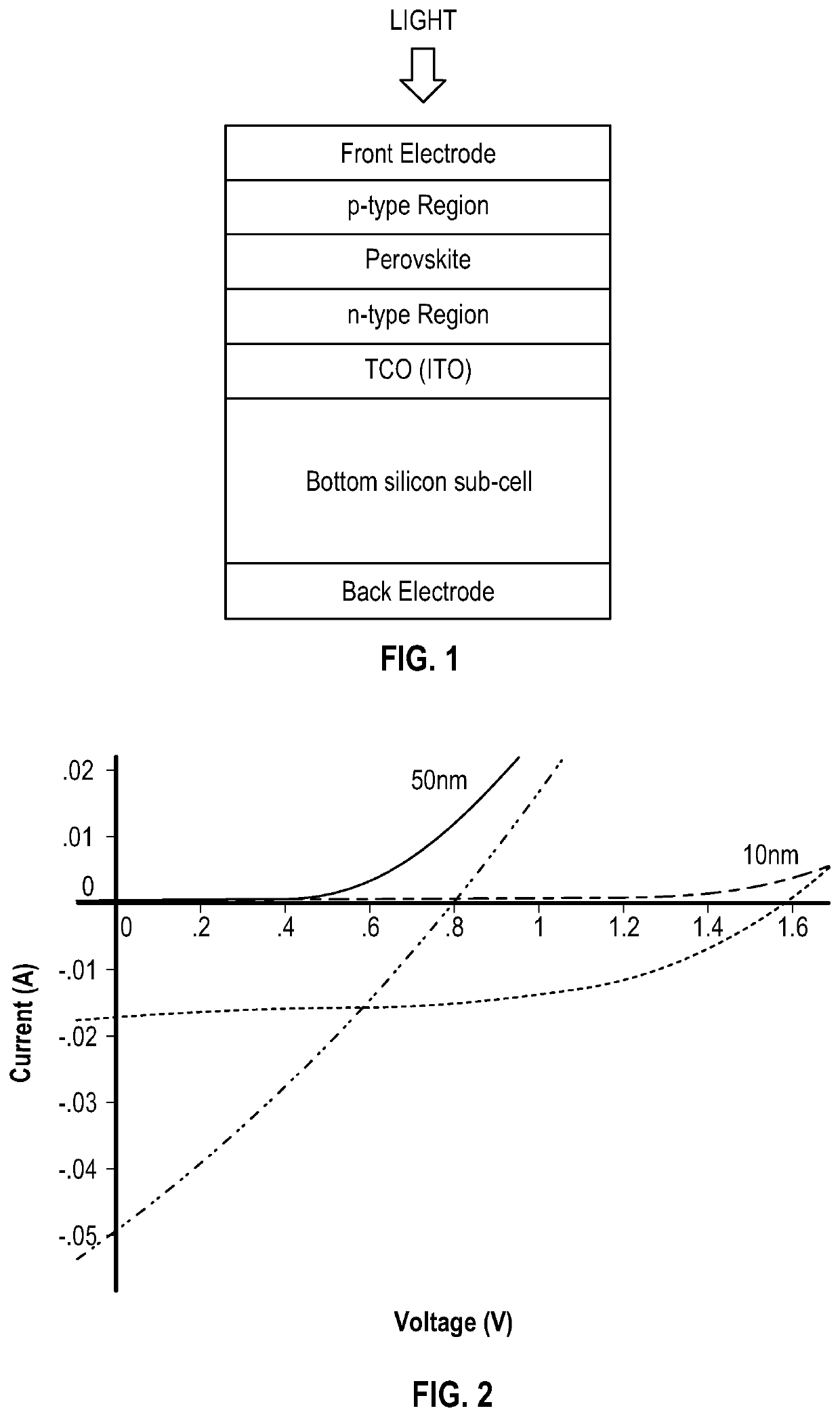
[0050]The term “photoactive”, as used herein, refers to a region, layer or material that is capable of responding to light photoelectrically. A photoactive region, layer or material is therefore capable of absorbing the energy carried by photons in light that then results in the generation of electricity (e.g. by generating either electron-hole pairs or excitons).

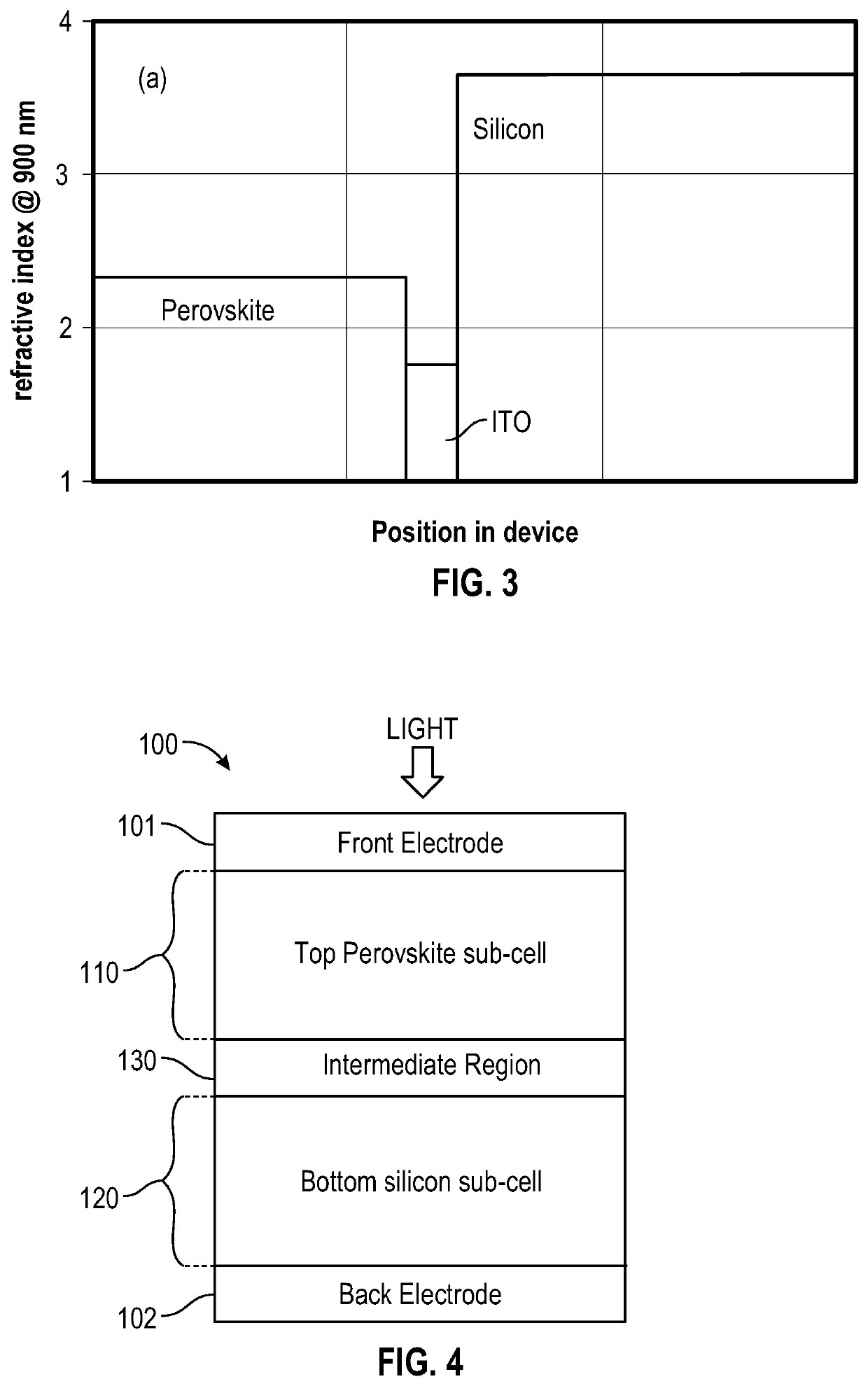
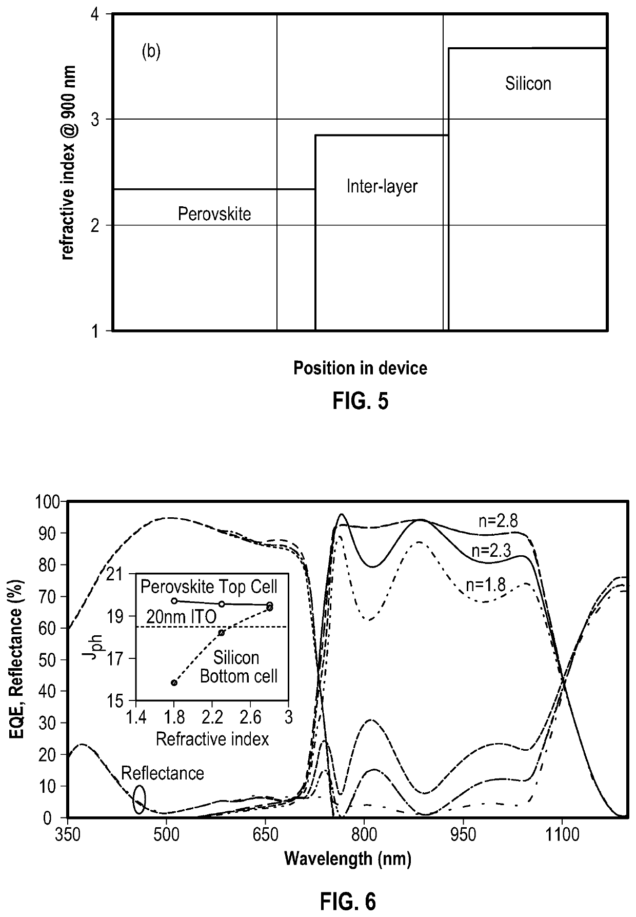
[0051]The term “perovskite”, as used herein, refers to a material with a three-dimensional crystal structure related to that of CaTiO3 or a material comprising a layer of material, which layer has a structure related to that of CaTiO3. The structure of CaTiO3 can be represented by the formula ABX3, wherein A and B are cations of different sizes and X is an anion. In the unit cell, the A cations are at (0,0,0), the B cations are at (½, ½, ½) and the X anions are at (½, ½, 0). The A cation is usually larg...


PUM


Abstract

There is provided a multi junction photovoltaic device comprising a first sub-cell comprising a photoactive region comprising a layer of perovskite material, a second sub-cell comprising a photoactive silicon absorber. and an intermediate region disposed between and connecting the first sub-cell and the second sub-cell. The intermediate region comprises an interconnect layer, the interconnect layer comprising a two-phase material comprising elongate (i.e. filament like) silicon nanocrystals embedded in a silicon oxide matrix.

Description

FIELD OF THE INVENTION[0001]The present invention relates to a monolithically integrated perovskite-on-silicon multi-junction photovoltaic device.BACKGROUND OF THE INVENTION[0002]Over the past forty years or so there has been an increasing realisation of the need to replace fossil fuels with more secure sustainable energy sources. The new energy supply must also have low environmental impact, be highly efficient and be easy to use and cost effective to produce. To this end, solar energy is seen as one of the most promising technologies, nevertheless, the high cost of manufacturing devices that capture solar energy, including high material costs, has historically hindered its widespread use.[0003]Every solid has its own characteristic energy-band structure which determines a wide range of electrical characteristics. Electrons are able to transition from one energy band to another, but each transition requires a specific minimum energy and the amount of energy required will be differe...

Claims


Application Information

Patent Timeline
IPC IPC(8): H01L31/0725H01L51/42H01L27/30H01L31/028H01L31/02H01L31/0224
CPCH01L31/028H01L27/302H01L31/02008H01L31/022466H01L31/0725H01L51/4246H01L31/043Y02E10/544H10K30/57H10K30/211Y02E10/549H10K85/50H01L31/0687H01L31/0352Y02E10/547
Inventor KIRNER, SIMON
Owner OXFORD PHOTOVOLTAICS
Why Eureka
Try Eureka