Liquid crystal display element

a liquid crystal composition and liquid crystal technology, applied in the direction of liquid crystal compositions, instruments, chemistry apparatus and processes, etc., can solve the problems of troublesome and time-consuming to find out the conditions for optimization, slow optical switching of nematic liquid crystals, and inability to adjust the temperature of liquid crystals, etc., to achieve fast decay time

Inactive Publication Date: 2020-03-05
DAINIPPON INK & CHEM INC
View PDF0 Cites 0 Cited by
  • Summary
  • Abstract
  • Description
  • Claims
  • Application Information

AI Technical Summary

Benefits of technology

[0021]According to the present invention, there is provided, in the field of liquid crystal display elements with polymer-stabilized alignment liquid crystals of polymer-network type, including tilt-imparted ones obtained through UV irradiation of a polymerizable liquid crystal composition, a liquid crystal display element whose drive voltage can be reduced with a fast decay time maintained and that is well balanced between changes over time in characteristics, such as decay time, drive voltage, and transmittance, and the voltage holding ratio. A polymerizable liquid crystal composition for use in it is also provided.

Problems solved by technology

Nematic liquid crystals, however, are slow in optical switching, approximately tens of milliseconds to milliseconds.
However, as a result of the recent increase in the size of liquid crystal TVs, the movement of things on the screen has become even faster.
It is therefore troublesome and time-consuming to find out the conditions for optimization.
Worse yet, even if optimization is tried, there is a trade-off between decay time and drive voltage: raising the drive voltage will increase the decay time, and lowering the drive voltage will reduce the decay time.
This makes it difficult to reduce the drive voltage while keeping a high level of decay time.
A known disadvantage of this method is that if the amount of ultraviolet radiation used is not sufficient for the monomer to polymerize, characteristics change over time.
However, too much ultraviolet radiation may result in chemical deterioration of the liquid crystal material caused by the ultraviolet irradiation.
With the liquid crystal display element described in PTL 5, therefore, it is difficult to achieve a balance between changes over time in characteristics, such as decay time, drive voltage, and transmittance, and the voltage holding ratio.

Method used


Image

  • Liquid crystal display element
  • Liquid crystal display element
  • Liquid crystal display element

Examples


example 1

[0725](Adjustment of Polymerizable Liquid Crystal Composition)

[0726]As an N-type liquid crystal composition, the composition represented by (LCN-1) below (Δn, 0.102; viscosity η, 16.8; Δε, −3.8) was prepared. The N-type liquid crystal composition (LCN-1) was heated to 60° C. and mixed with a solid polymerizable compound (V1-1-1) until dissolution. The mixture was observed under a polarized light microscope, and it was confirmed that polymerizable compound (V1-1-1) was dissolved uniformly and exhibited a nematic liquid crystal phase at room temperature. To this solution, photopolymerization initiator (I-1) was added. In this way, a polymerizable liquid crystal composition was prepared.

[0727](Fabrication of Liquid Crystal Display Element and Evaluation of Electrooptical Characteristics)

[0728]For the resulting liquid crystal to achieve a uniaxial alignment (homogeneous alignment), vertical alignment films coated with a polyimide vertical alignment film and having a cell gap of 3.6 μm w...

examples 2 and 3

[0733]The photopolymerization initiator was (I-1), and the composition of Example 2 or 3 in Table 1 was filled into a cell in the same way as in Example 1.

[0734]After the filling, the glass cell was taken out, and its opening for filling was sealed with a sealant 3026B (ThreeBond). Using an ultraviolet LED light source with a wavelength of 365 nm, the cell was irradiated with ultraviolet radiation at an intensity of 20 mW / cm2 at 25° C. for 60 seconds.

[0735]After the completion of ultraviolet irradiation, the alignment of the liquid crystal in the cell was observed under a polarized light microscope with the cell positioned to make the direction of rubbing at an oblique angle of 450 with respect to any of crossed-nicols polarizers. In the voltage-off state, there was a dark field, indicating that the liquid crystal was completely in a substantially vertical alignment. When the voltage applied was increased gradually, the cell became brighter as a result of its slitted section transit...

examples 4 and 5

[0740]As a liquid crystal composition having a P-type dielectric anisotropy, the composition represented by the formula (LCP-1) below (Δn, 0.109; viscosity η, 24 mPa·s; Vth, 1.62 Vrms) was prepared. The polymerizable compound was the compound represented by (V1-1-1) below.

[0741]A polymerizable liquid crystal composition was prepared that contained 98% to 97% by mass P-type liquid crystal composition (LCP-1), 1.96% to 2.94% by mass polymerizable compound (V1-1-1), and photopolymerization initiator (I-1) making up 2% by mass of polymerizable compound (V1-1-1).

[0742]For the resulting liquid crystal to achieve a uniaxial alignment (homogeneous alignment), a parallel-rubbed cell including ITO coated with a polyimide alignment film and having a cell gap of 3.6 μm was used. The polymerizable liquid crystal composition as a mixture of (LCP-1), (V1-1-1) and (I-1) was heated to 60° C. for dissolution and then filled into the glass cell by vacuum filling.

[0743]After the filling, the opening fo...


PUM

PropertyMeasurementUnit
nematic-isotropic transition temperature TNIaaaaaaaaaa

Abstract

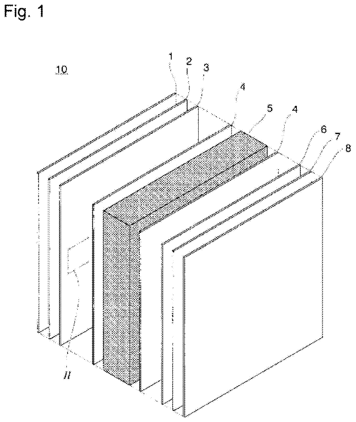
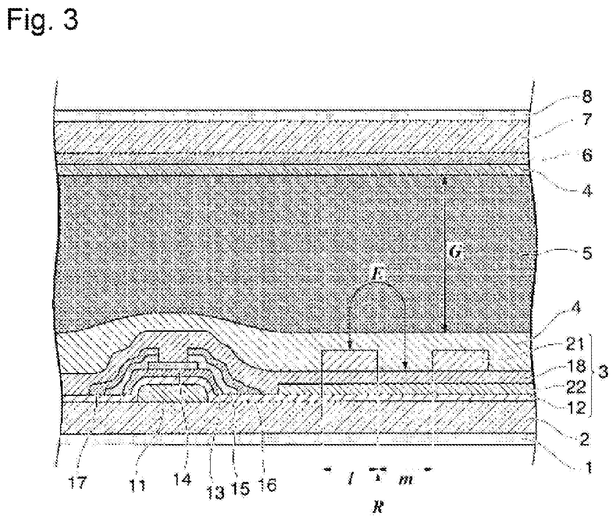
“Object” To provide a tilt-imparted liquid crystal display element that is obtained through UV irradiation of a polymerizable liquid crystal composition, whose drive voltage can be reduced with a fast decay time maintained, and that is well balanced between characteristics, such as decay time, drive voltage, and transmittance. A polymerizable liquid crystal composition for use in it is also provided. “Solution” A liquid crystal display element has polymer networks formed in the liquid crystal phase 5 in FIG. 3. The polymer networks are formed by polymerizing a polymerizable liquid crystal composition that contains, as essential ingredients, a radically polymerizable monomer component (A), a liquid crystal material (B), and a polymerization initiator (C) that has a molecular structure resulting from substituting any two or more hydrogen atoms in the aromatic nucleus in the molecular structure of an alkylphenone-based photopolymerization initiator, for example with a C1-10 alkyl group (i).

Description

TECHNICAL FIELD[0001]The present invention relates to a polymerizable liquid crystal composition, a liquid crystal display element, and a method for producing a liquid crystal display element.BACKGROUND ART[0002]Liquid crystal materials are commonly used in flat-panel displays, for example of TVs, monitors, cellular phones, smartphones, and tablet computers. Nematic liquid crystals, however, are slow in optical switching, approximately tens of milliseconds to milliseconds. Seeking faster display, the field of already widespread liquid crystal TVs often employs PS (polymer-stabilised) or PSA (polymer-sustained alignment) displays. They primarily use, for example, the vertical alignment mode and their rise time are accelerated in the voltage-on state (on-response) by virtue of a tilt angle given to the liquid crystal material (see PTL 1 to 5).[0003]Such a PS or PSA display is specifically obtained by adding 0.3% by mass or more and less than 1% by mass polymerizable compound to the li...

Claims


Application Information

Patent Timeline
Patent Type & Authority Applications(United States)
IPC IPC(8): C09K19/38C09K19/54C09K19/30C09K19/22C09K19/20C09K19/34C09K19/12C09K19/32C09K19/18
CPCC09K19/3852C09K2019/304C09K19/3003C09K19/22C09K19/2014C09K19/3402C09K19/12C09K19/322C09K19/18C09K19/3028C09K2019/3009C09K2019/301C09K2019/3016C09K2019/2035C09K2019/2042C09K2019/2078C09K2019/3422C09K2019/122C09K2019/123C09K19/54C09K19/14C09K19/20C09K19/30C09K19/32C09K19/34C09K19/3472C09K19/38C09K2019/0448C09K2019/3425G02F1/13G02F1/1337
Inventor FUJISAWA, TORUIWAKUBO, MASAYUKIHASEBE, HIROSHIKODERA, FUMIAKIJANG, KEUMHEE
Owner DAINIPPON INK & CHEM INC
Why Eureka
Try Eureka