Methods and systems for detection of ion spatial distribution

a technology of ion spatial distribution and detection method, applied in the field of mass spectrometry, can solve the problems of reducing the resolution of m/z, the weekly calibration schedule, and the suggestion of longevity experiments, and achieves the effects of reducing the rate of response degradation, reducing the rate of exposure, and reducing the rate of aging

Active Publication Date: 2020-03-12
THERMO FINNIGAN
View PDF0 Cites 0 Cited by
  • Summary
  • Abstract
  • Description
  • Claims
  • Application Information

AI Technical Summary

Benefits of technology

[0032]The above-outlined methods, in which either the ion beam or a transducer is repositioned or migrated, assures that the ion beam or electron beam does not remain stationary at any one particular position of the associated transducer for an extended period of time, thereby reducing the rate of response degradation across the transducer surfaces and permitting an imaging mass spectrometer ion detector to operate for extended periods of time between calibrations. These methods may be employed in conjunction with a known time and position imaging mass spectrometer detector system, such as one of the detector systems illustrated in FIG. 1C and FIG. 2 or other such systems as described in U.S. Pat. No. 8,389,929, which is hereby incorporated by reference in its entirety. Alternatively, these methods may be employed in conjunction with a time and position imaging mass spectrometer detector system that is modified with either one or both of the modifications illustrated in FIG. 5B.
[0033]According to another set of methods in accordance with the present teachings, a time and position imaging mass spectrometer is operated such that a supplemental low-frequency alternating-current (AC) voltage waveform is applied to rods of the quadrupole. The frequency (or component frequencies) of the AC wave is / are chosen to match to the secular frequency or frequencies of targeted mass-to-charge ratios during a mass analysis experiment. This low-frequency AC waveform may be phase synchronized to the scanning RF waveform and can be applied on either two pairs of the rods with opposite phase or on just one opposing pair of the rods. As is well known in the art of mass spectrometry, such resonant excitation imparts additional energy to the ions comprising the targeted m / z values, thus increasing the oscillation amplitude of such excited ions. The amplitude of the AC waveform is chosen such the ions having the targeted m / z values are caused to have a greater probability of being detected away from (instead of within) the zone of ion focusing and such that the targeted ions are not laterally ejected from the interior of the quadrupole. The increased oscillation amplitude of these ions causes a diminishing of ion flux at the center of a transducer, thus reducing the rate of aging of the transducer within the mass spectrometer.
[0034]According to another set of methods in accordance with the present teachings, a transducer (either an MCP or a scintillator) may be “pre-aged” prior to putting the transducer into service within a time and position imaging mass spectrometer system. The pre-aging may be effected by causing a beam of electrons to impinge upon all or a portion of a surface of a transducer, under the impetus of an electrical potential difference between the emitter and the transducer. Once placed into service within a mass spectrometer, the pre-aged portions of the transducer will be less susceptible to additional degradation of transducer response as compared to non-aged transducers or non-aged portions of a single transducer. By this means, the duration of the validity of mass spectrometer detector calibrations may be prolonged once the transducer is placed into service, since the utility of such calibrations depends upon constancy of detector response.

Problems solved by technology

Such conventional operation creates a trade-off between instrument resolution and sensitivity.
Conversely, high sensitivity or high speed can also be achieved during conventional operation, but only by widening the pass band, thus causing degradation of m / z resolution.
A weekly calibration schedule, as suggested by longevity experiments, may not be acceptable for most users.
Similar to the effect of physical movement of the transducers, the execution of this method may cause an ion beam to gradually migrate about the surface of the MCP.

Method used


Image

  • Methods and systems for detection of ion spatial distribution
  • Methods and systems for detection of ion spatial distribution
  • Methods and systems for detection of ion spatial distribution

Examples


Embodiment Construction

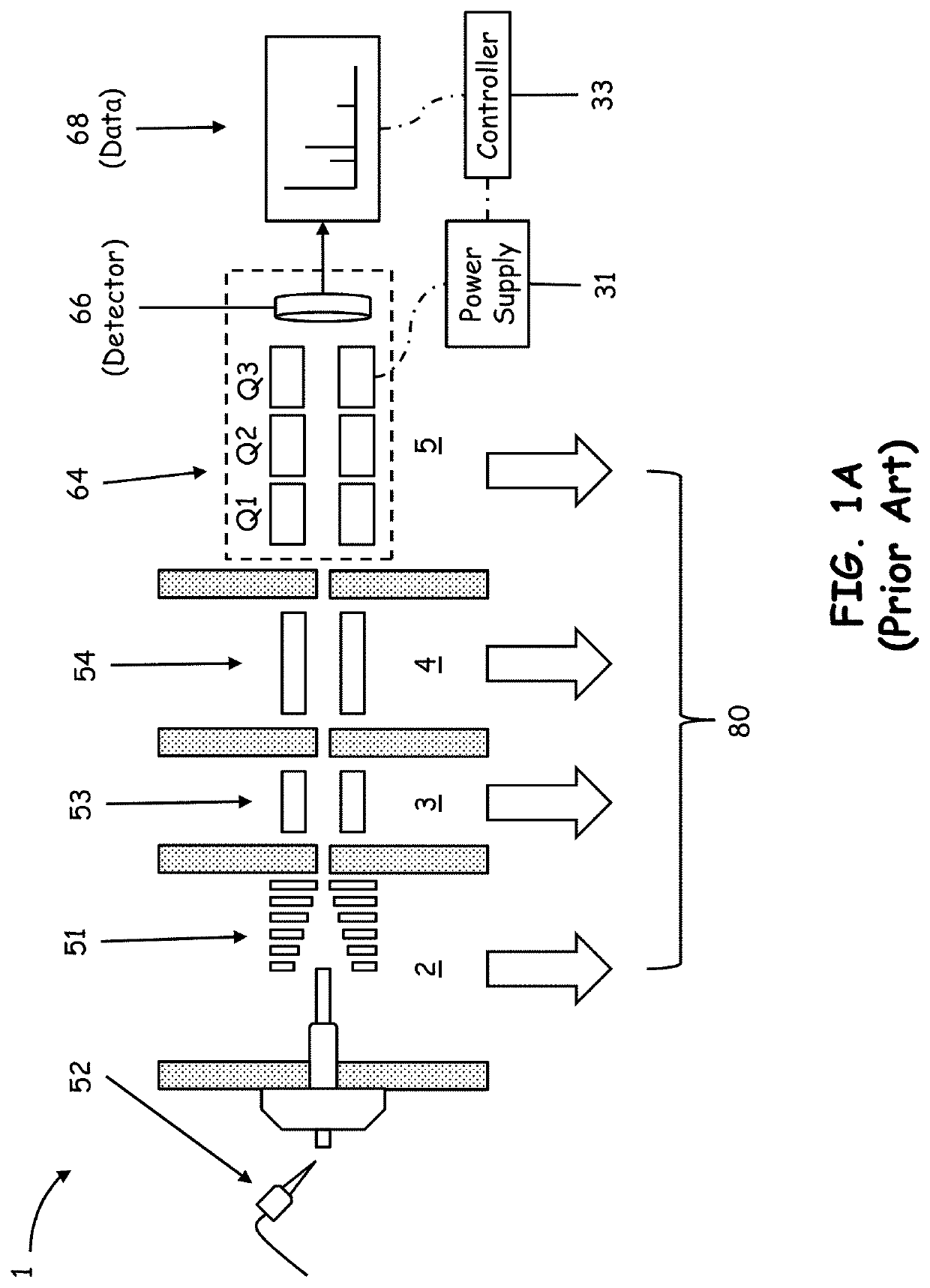
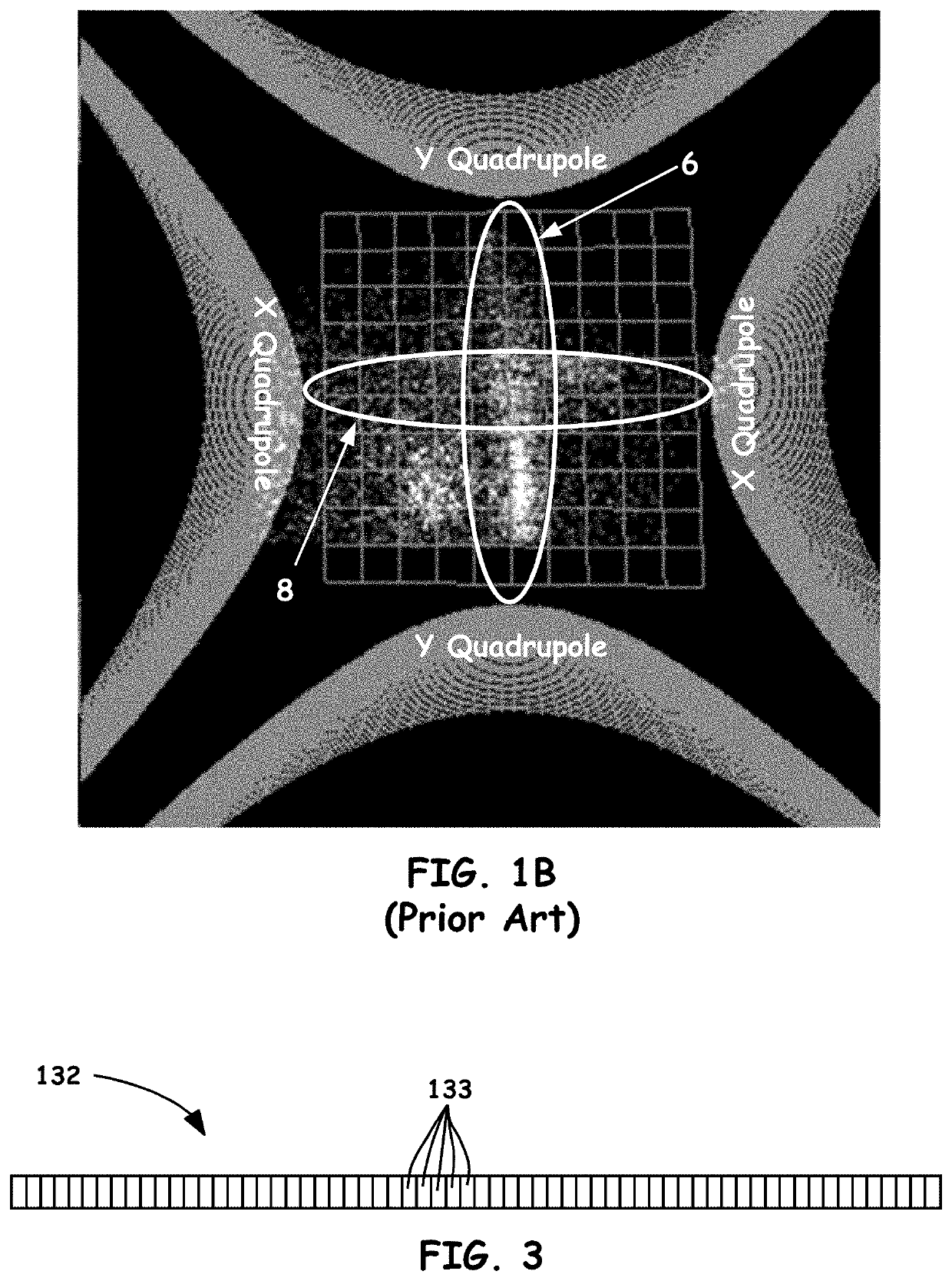
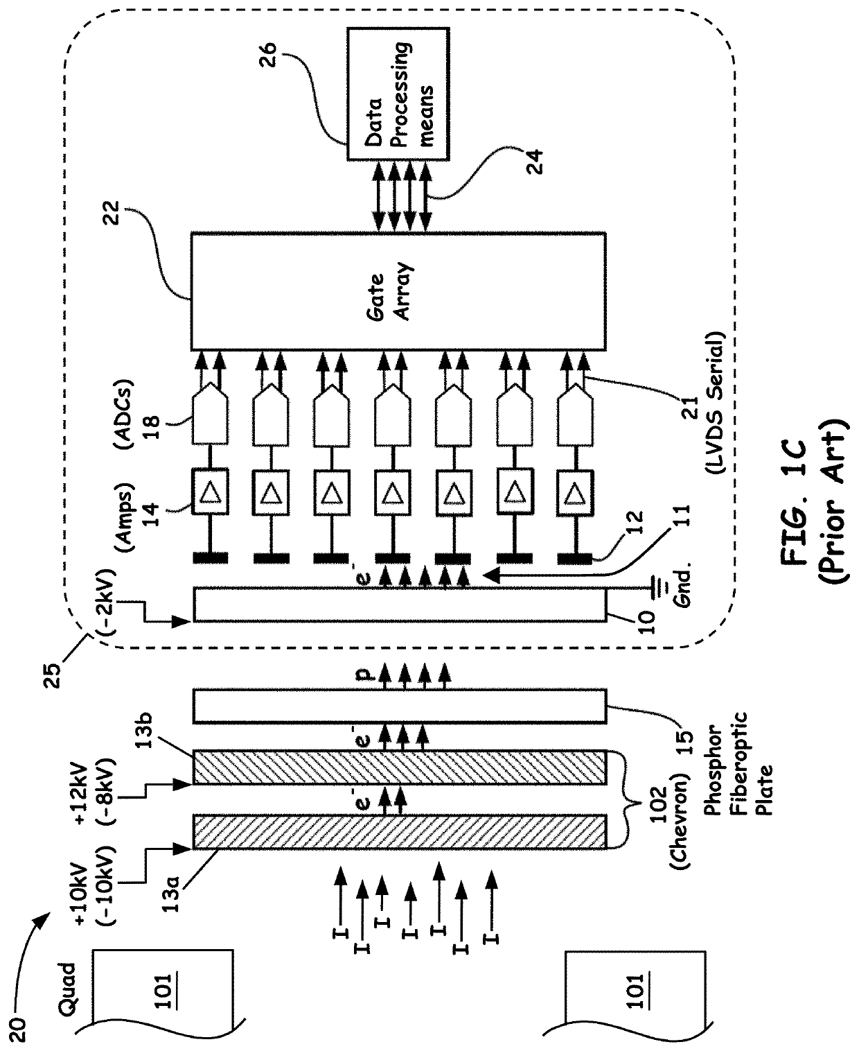
[0065]The following description is presented to enable any person skilled in the art to make and use the invention, and is provided in the context of a particular application and its requirements. Various modifications to the described embodiments will be readily apparent to those skilled in the art and the generic principles herein may be applied to other embodiments. Thus, the present invention is not intended to be limited to the embodiments and examples shown but is to be accorded the widest possible scope in accordance with the features and principles shown and described. The particular features and advantages of the invention will become more apparent with reference to the appended FIGS. 1-13.

[0066]In the description of the invention herein, it is understood that a word appearing in the singular encompasses its plural counterpart, and a word appearing in the plural encompasses its singular counterpart, unless implicitly or explicitly understood or stated otherwise. Furthermore...


PUM


Abstract

A method of performing mass spectrometric analyses, comprises: (a) passing a stream of ions through a quadrupole mass analyzer; (b) intercepting a flux of ions emitted from an exit aperture of the quadrupole mass analyzer at a front face of a stack of multichannel plates and emitting a flux of electrons in response to the intercepted flux of ions at a rear face of the stack of multichannel plates; (c) intercepting the flux of electrons at a front surface of a scintillator comprising a phosphorescent material and emitting a flux of photons in response to the intercepted flux of ions at a rear surface of the scintillator; (d) receiving the flux of photons at a photo-imager; and (e) repositioning at least one of the scintillator and the stack of microchannel plates during the execution of one or more of the steps (a) through (d).

Description

CROSS REFERENCE TO RELATED APPLICATION[0001]This application is a Divisional of and claims, under 35 U.S.C. 120, the right of priority to and the benefit of the filing date of co-pending U.S. patent application Ser. No. 16 / 038,546, now U.S. Pat. No. 10,490,397, filed on Jul. 18, 2018, the disclosure of which is incorporated by reference herein in its entirety.FIELD OF THE INVENTION[0002]The present invention relates to the field of mass spectrometry. More particularly, the present invention relates to mass spectrometer detector systems and methods in which ions exiting a quadrupole mass analyzer are converted to a quantity of electrons and said electrons are converted to a quantity of photons that are focused onto an image plane and imaged by a photo-imager.BACKGROUND OF THE INVENTION[0003]Quadrupole mass filters are often employed as a component of a triple stage mass spectrometry system. By way of non-limiting example, FIG. 1A schematically illustrates a triple-quadrupole system, ...

Claims


Application Information

Patent Timeline
Patent Type & Authority Applications(United States)
IPC IPC(8): H01J49/42H01J49/02H01J49/00
CPCH01J49/025H01J49/0031H01J49/0036H01J49/4215H01J49/063H01J49/26H01J49/06G01N27/62H01J49/0004
Inventor CHEN, TSUNG-CHI
Owner THERMO FINNIGAN
Why Eureka
Try Eureka