Optical combiner and applications thereof

a combiner and optical technology, applied in the field of optics, can solve the problems of limited interaction length of the waves interacting with said substances, destructive and constructive interference of forward and backward propagating waves, and the inability to apply methods in the case of deep grating grooves, etc., to achieve shorten the spectral width of the outcoupled light, increase or decrease the effect of outcoupling efficiency and limited optical perturbations

Active Publication Date: 2020-03-26
CSEM CENT SUISSE DELECTRONIQUE & DE MICROTECHNIQUE SA RECH & DEV
View PDF1 Cites 12 Cited by
  • Summary
  • Abstract
  • Description
  • Claims
  • Application Information

AI Technical Summary

Benefits of technology

[0032]The outcoupling grating can be fully engineered to outcouple and redirect portions of the waveguided light to any direction in a 3D configuration, especially by engineering its orientation and spatial periodicity in accordance with the waveguiding layer. As well as the incoupling grating, the outcoupling grating can be designed to be non-linear, as examples curved or segmented, so as to modify the wavefront and collimation of the redirected light perpendicular to the waveguiding propagation axis, the outcouping grating can be designed to have gradiant spatial periodicity to also modify the wavefront and collimation of the redirected light over the waveguiding propagation axis. The grating depth, also called the RWG corrugation, and the waveguiding layer permittivity contrast with its environment can be modified to broaden or shorten the spectral width of the outcoupled light as well as to increase or decrease the outcoupling efficiency. It can be designed to outcoupled light in various spatial location in various directions and collimation to create multiple beamlets, eventually interfering with each other given their common light source being in the guided light.
[0033]The many degrees of freedom in the design and engineering of optical combiner using pairs of RWG, and their intrinsic chromatic and angular specificity, allow many optical configurations, for example with complex lateral and vertical stacking while having extremely limited optical perturbations between various different arrangements as well as for the light impeding from the outside world. By arranging a plurality of pairs of RWG, an imaging optical combiner can be realized. Such combiners can be arranged to be multichromatic and to have provide a large color gamut, to have a high resolution defined perpendicular to the viewing direction, to provide various virtual image focal depth in the viewing direction in so-called light-field display configurations, to have extended exit pupils, to provide large FOV while being very thin, lightweight, possibly conformable to any 2D curves survace and being affordable for mass production.

Problems solved by technology

Because the waveguide is intrinsically corrugated being a waveguide-grating, the guided modes are necessarily leaky, a fraction of the guided light is outcoupled travelling through each grating period while another portion is incoupled under suitable impending light.
Because of their small periodicity, they do not allow various diffractive orders, which distinguishes them from diffractive optical elements (DOE) such as surface relief grating (SRG), Holographic Optical elements (HOE) such as volume holograms and Switchable Bragg Grating (SBG).
This method cannot be applied in the case of deep grating grooves.
Rosenblatt and Sharon explained in these papers that the efficient transfer of wave energy between forward and backward propagations at resonance is due to the relative phase-shift between the incident and the diffracted waves, resulting in destructive and constructive interference of forward and backward propagating waves.
A limitation of guided mode resonance devices in sensors is that the interaction length of the waves interacting with said substances is limited due to the leaky-mode propagations.
In this device the major drawback is the inherent leakage of light along the waveguide, therefore the resonant light cannot be absorbed completely by the medium in contact with the waveguide.
Merging high resolution color images, typically made by RGB components, without disturbing the natural field of view has been proven challenging.
However, these diffractive elements are highly dispersive and are relatively broadband, creating so-called “rainbow-effect”, possibly for both the external world light and computed images.
This limits the application of diffractive optical elements as optical combiner mostly to outcouple light rays from lightguides, so that most of the diffracted light from the external world is diffracted and the lightguide, limiting the visual aberations.
Current limitations are, depending of the approaches used: chromatic dispersions, diffraction of light coming from the outside world, limited transparency, limited shape to planar waveguides used for Exit Pupil Expansion (EPE), limited FOV and difficult manufacturing fabrication / replications processes and fabrication tolerances.

Method used


Image

  • Optical combiner and applications thereof
  • Optical combiner and applications thereof
  • Optical combiner and applications thereof

Examples


Embodiment Construction

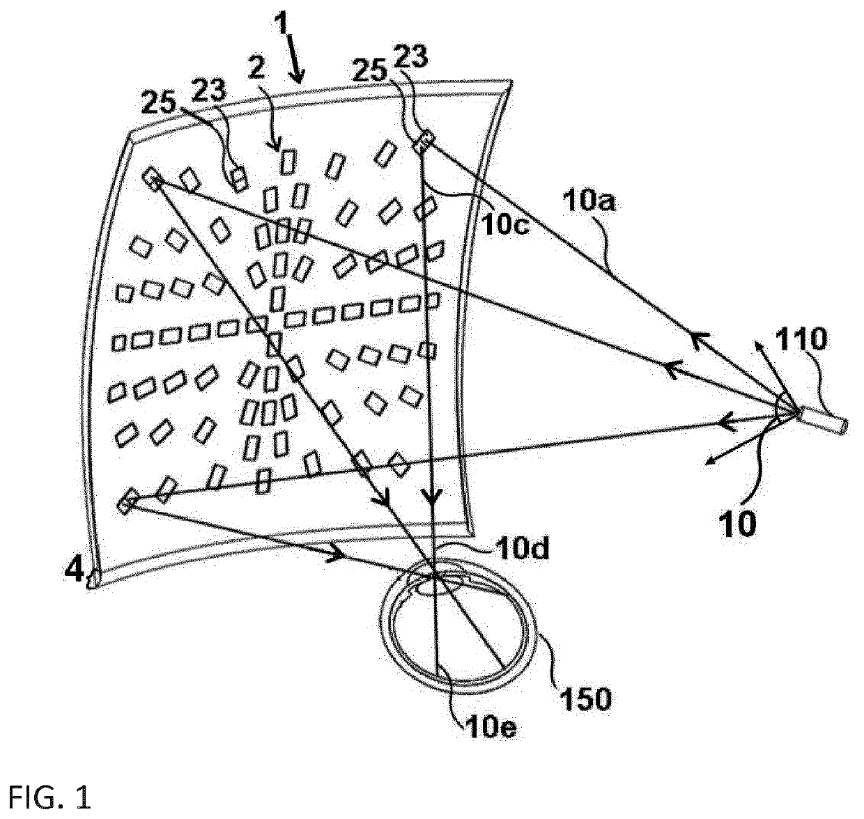
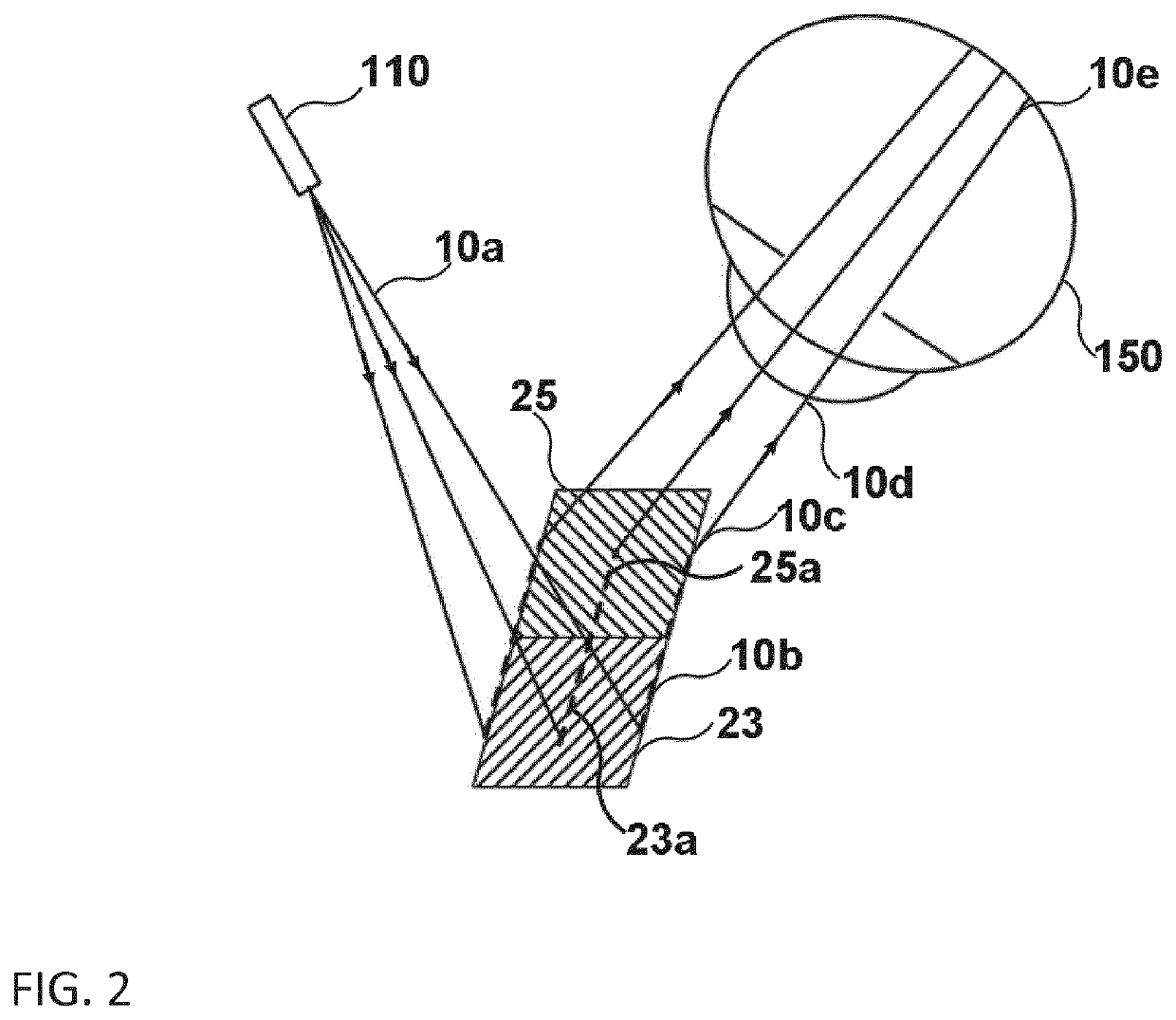
[0076]The following detailed description is directed to certain specific embodiments of the invention. However, the invention can be embodied in a multitude of different ways. In this description, reference is made to the drawings wherein like parts are designated with like numerals throughout. As will be apparent from the following description, the embodiments of the optical combiner may be implemented in any device that comprises said optical combiner. More specifically the optical combiner may be implemented in a near-to-eye display apparatus.

[0077]The near-to-the-eye display apparatus 100 of the invention, also defined as display, comprises at least said optical combiner 1 and a light source, also defined as image projector, microdisplay or light emitter 110, as illustrated in FIG. 23. The light emitter 110 emits a light beam 10 in the direction of the optical combiner 1. The optical combiner 1 has a front side 1a situated to the side of a scene, defined as front side, and a bac...


PUM

PropertyMeasurementUnit
wavelengthaaaaaaaaaa
thicknessaaaaaaaaaa

Abstract

An optical combiner including an array of pairs of resonating waveguide gratings. The waveguiding layer of the array, which includes the resonating waveguide gratings, is configured to guide at most ten guided light modes in the visible wavelength range. At least a portion of the resonating waveguide grating array is configured to incouple a portion of incident light on the array and to outcouple a fraction of that incident light. The outcoupled fraction has a predetermined wavelength λ in the visible and near-infrared wavelength range and has a predetermined spectral width Δλ. The optical combiner is preferably configured to be used in a near-eye display apparatus. The invention is also achieved by a near-eye display apparatus that is adapted to combine projected images provided by a light emitter with light provided by a scene observed by an observer looking through the optical combiner.

Description

FIELD OF THE INVENTION[0001]The invention relates to the field of optics and in particular, but not exclusively, to near-to-eye optical systems. More particularly the invention relates to optical systems that are based on arrays of resonating grating elements and to virtual image display apparatus that are suitable for head-mounted displays mounted on the head of an observer.BACKGROUND OF THE INVENTION[0002]Resonant waveguide gratings (defined as RWG hereafter, also called resonating waveguide gratings), also called leaky-mode waveguide, low-modes waveguide gratings, subwavelength waveguide gratings, zero-order devices and guided-mode resonance filters or devices, and comprising monomode waveguide gratings, have been developped since more than 30 years.[0003]Gratings have also been used widely as devices to disperse and filter optical beams. The combination of gratings and waveguides has been proposed to make optical structures and devices with unique properties such as filters havi...

Claims


Application Information

Patent Timeline
Patent Type & Authority Applications(United States)
IPC IPC(8): G02B27/01G06F3/01G02B27/10F21V8/00
CPCG02B27/1086G02B2027/0118G02B2027/0178G02B6/0016G02B6/0036G02B27/0172G06F3/013B42D25/328
Inventor BASSET, GUILLAUMEQUARANTA, GIORGIO
Owner CSEM CENT SUISSE DELECTRONIQUE & DE MICROTECHNIQUE SA RECH & DEV
Why Eureka
Try Eureka