Process for manufacturing an aluminum alloy part

Pending Publication Date: 2020-05-21
C TEC CONSTELLIUM TECH CENT
View PDF0 Cites 5 Cited by
  • Summary
  • Abstract
  • Description
  • Claims
  • Application Information

AI Technical Summary

Benefits of technology

The patent describes a method of manufacturing materials using a process called additive manufacturing, which allows for the tolerance of higher amounts of impurities such as Mn, Ti, V, Zr, and Cr. These impurities can normally degrade the mechanical properties of the material, but the additive manufacturing process allows for the formation of dispersoids or thin intermetallic phases that increase the hardness of the material. Additionally, the method includes steps to improve the surface quality, corrosion resistance, and fatigue crack growth resistance of the material. Overall, the method allows for the production of high-quality materials with improved mechanical properties.

Problems solved by technology

However, owing to a too high variability in the magnesium content thereof, the mechanical performance levels can vary from one point of the part to another, and in particular as a function of the height of the wall formed.
Such heterogeneity is not compatible with the requirements for certain technical fields, for example aeronautics.

Method used


Image

  • Process for manufacturing an aluminum alloy part
  • Process for manufacturing an aluminum alloy part
  • Process for manufacturing an aluminum alloy part

Examples


example 1

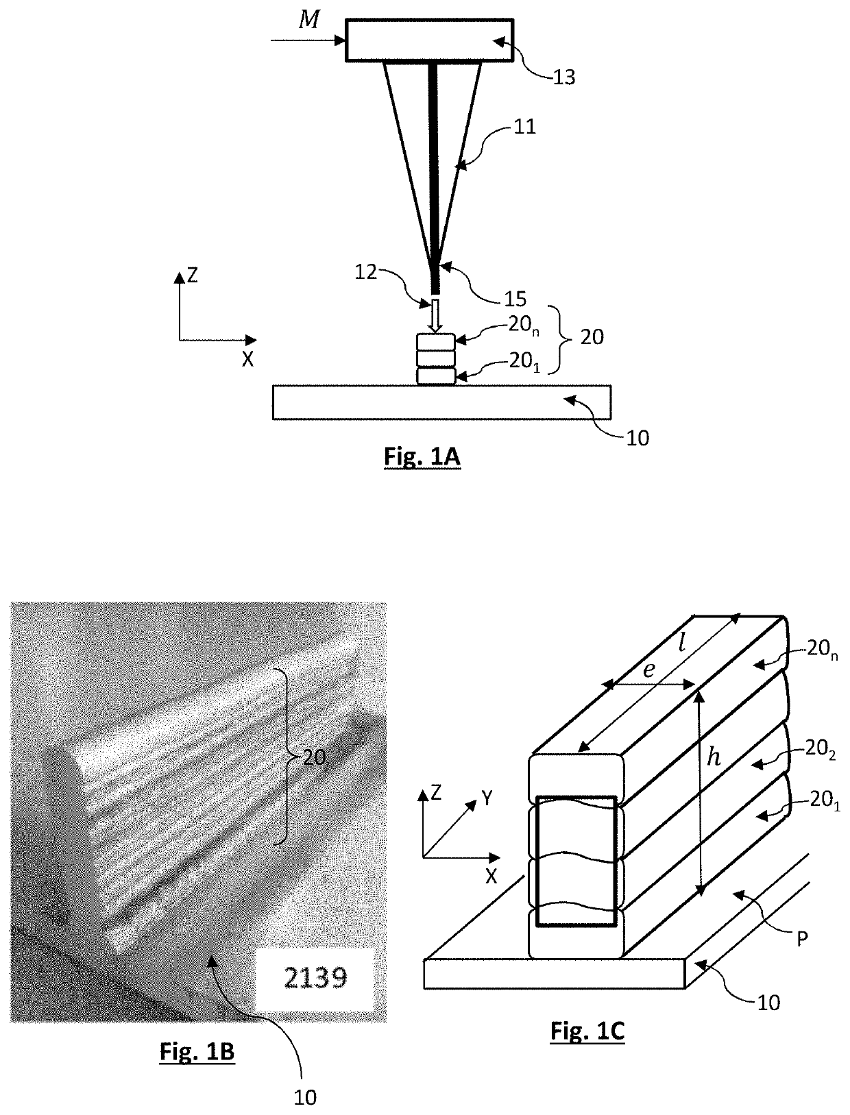
[0092]A plurality of filler wires 15 were used in order to manufacture different walls:[0093]alloy 2319 wires corresponding to industrial welding wires;[0094]alloy 2219 and 2139 wires obtained from cast prototype alloys, the wires being obtained by extrusion and wire drawing from billets having a diameter of 55 mm and a length of 150 mm.

[0095]In this example, the filler wire had a diameter of 1.2 mm. An inert gas welding power source available under the reference FK 4000-RFC by Fronius and a Motoman MA210 welding robot by Yaskawa were used.

[0096]The walls had a thickness e in the range 4 mm to 6 mm. The walls had a length l of 10 cm and a height h of 3 cm.

[0097]The parameters for the implementation of the WAAM method were as follows:[0098]torch travel speed: 42 cm / min;[0099]wire feed rate: in the range 5 to 9 m / min;[0100]test conducted at atmospheric pressure.

[0101]The chemical composition of the walls was measured by mass spectrometry of ICP-OES type (inductively coupled plasma—opt...

example 2

[0123]Another series of tests was conducted using a filler material formed by a 2295 alloy. Walls 20 similar to those described hereinabove were produced again by implementing a WAAM method at atmospheric pressure. The chemical composition, in terms of weight percentage, of each wall was as follows:

TABLE 2LiSiFeCuMnMgTiAgVZr1.080.020.044.530.340.180.020.230.15

[0124]Measurements performed on the filler wire did not reveal any significant deviations between the composition of the filler wire and the walls formed therefrom.

[0125]The walls 20 then underwent T6 treatment or T6 treatment preceded by a hot isostatic compression (HIP) step. During the T6 treatment, solution heat treatment was carried out for 2 h at a temperature of 529° C. and aging was carried out for 100 h at a temperature of 160° C.

[0126]FIG. 2F shows the Vickers Hardness HV 0.1 values for the walls 20 obtained by implementing different alloys, these measurements having been performed according to standard NF EN ISO 6507...

example 3

[0137]In this example, walls were produced by the SLM method described hereinabove. In the following tests, the laser source 31 is a Nd / Yag laser with a power of 400 MW.

[0138]Cubic parallelepipeds of dimensions 1 cm×1 cm×1 cm were formed according to this method, by stacking different layers formed, the powder 25 being obtained from aluminium alloy 2139.

[0139]The composition of the powder was determined by ICP-OES and is given as a weight percentage in the following table.

TABLE 3SiFeCuMnMgTiAgVZr0.040.094.80.290.390.050.34

[0140]A particle size analysis was conducted according to standard ISO 1332 using a Malvern 2000 particle size analyser. The curve describing the evolution in the volume fraction as a function of the diameter of the particles forming the powder describes a distribution similar to a Gaussian distribution. If d10, d50 and d90 respectively represent the fractiles at 10%, at 50% (median) and at 90% of the distribution obtained, a rate of uniformity

σ=d90-d10d50

and a sta...


PUM

PropertyMeasurementUnit
Fractionaaaaaaaaaa
Fractionaaaaaaaaaa
Fractionaaaaaaaaaa

Abstract

The present invention relates to a process for manufacturing a part (20) comprising a formation of successive metal layers (201 . . . 20n), superimposed on one another, each layer describing a pattern defined from a numerical model, each layer being formed by the deposition of a metal (15, 25), referred to as a filling metal, the filling metal being subjected, at a pressure greater than 0.5 times the atmospheric pressure, to an input of energy so as to melt and constitute said layer, the process being characterized in that the filling metal is an aluminium alloy of the 2xxx series, comprising the following alloying elements:Cu, in a weight fraction of between 3% and 7%;Mg, in a weight fraction of between 0.1% and 0.8%;at least one element, or at least two elements or even at least three elements chosen from:Mn, in a weight fraction of between 0.1% and 2%, preferably of at most 1% and in a preferred manner of at most 0.8%;Ti, in a weight fraction of between 0.01% and 2%, preferably of at most 1% and in a preferred manner of at most 0.3%;V, in a weight fraction of between 0.05% and 2%, preferably of at most 1% and in the preferred manner of at most 0.3%;Zr, in a weight fraction of between 0.05% and 2%, preferably of at most 1% and in a preferred manner of at most 0.3%;Cr, in a weight fraction of between 0.05% and 2%, preferably of at most 1% and in the preferred manner of at most 0.3%; andoptionally at least one element, or at least two elements or even at least three elements chosen from:Ag, in a weight fraction of between 0.1% and 0.8%;Li, in a weight fraction of between 0.1% and 2%, preferably 0.5% and 1.5%;Zn, in a weight fraction of between 0.1% and 0.8%.

Description

TECHNICAL FIELD[0001]The technical field of the invention is a method for manufacturing an aluminium alloy part, implementing an additive manufacturing technique.PRIOR ART[0002]Additive manufacturing techniques have been developing since the 1980s. These techniques consist of forming a part by adding material, as opposed to machining techniques, which aim to remove material. Formerly confined to prototyping, additive manufacturing is now operational in the serial manufacture of industrial products, including metal parts.[0003]The term “additive manufacturing” is defined according to the French standard XP E67-001 as a “set of processes making it possible to manufacture, layer by layer, by adding material, a physical object from a digital object”. Standard ASTM F2792 (January 2012) also defines additive manufacturing. Different additive manufacturing methods are also defined and described in standard ISO / ASTM 17296-1. The use of additive manufacturing to produce an aluminium part wit...

Claims


Application Information

Patent Timeline
IPC IPC(8): B22F7/00C22C1/04C22F1/057B22F3/105B23K15/00B23K26/00C22C21/16B22F3/15B23K26/342B23K35/02B22F3/24B33Y70/00B33Y80/00
CPCB33Y70/00C22C21/16C22F1/057B22F3/1055B22F2003/248B23K15/0086B22F7/008B23K26/0006B22F2998/10B22F3/15B23K35/0261B33Y80/00C22C1/0416B23K26/342Y02P10/25B22F10/62B22F10/64B22F10/28B22F10/66B22F10/25B22F3/16
Inventor CHEHAB, BECHIRBES, BERNARDCHABRIOL, CHRISTOPHELEDOUX, MARINEODIEVRE, THIERRY
Owner C TEC CONSTELLIUM TECH CENT
Why Eureka
Try Eureka