Supercharge Your Innovation With Domain-Expert AI Agents!

Method of controlling injector driving circuit

a driving circuit and injector technology, applied in the direction of electric control, machine/engine, pulse technique, etc., can solve the problems of affecting the operation of the injector, so as to prevent the damage of the zener diode, prevent the increase in the size of the component, and reduce the energy of the electromotive for

Inactive Publication Date: 2020-06-25
NIKKI CO LTD
View PDF0 Cites 0 Cited by
  • Summary
  • Abstract
  • Description
  • Claims
  • Application Information

AI Technical Summary

Benefits of technology

The invention provides a method for controlling an injector driving circuit that prevents damage to a Zener diode and reduces electromotive force energy when the injector is in an OFF state. This is achieved by turning off the first FET and then the second FET in a predetermined sequence to prevent damage to the Zener diode and ensure the injector operates safely and efficiently. This method can be used without increasing the size or cost of the circuit components.

Problems solved by technology

Incidentally, for example, in a natural gas fuel vehicle, due to the fact that water contained in methane gas in natural gas, moisture generated at the time of combustion, etc. freezes at low temperature, or when a valve of the injector is formed of rubber, etc., the valve of the injector sticks due to sticking, etc. of rubber, even when a starting current of a value set in advance at the beginning of the valve opening time is supplied for a set time, the valve of the injector is difficult to open, and there is a problem that engine startability deteriorates.
Thus, there is a problem that the Zener diode ZD1 is damaged, and it is necessary to increase the capacity of the Zener diode ZD1.
However, when the capacity is increased, a shape increases in size, requiring installation space.
Further, there is a problem that a part price is increased.

Method used


Image

  • Method of controlling injector driving circuit
  • Method of controlling injector driving circuit

Examples


Embodiment Construction

[0016]Next, an embodiment of the invention will be described with reference to drawings.

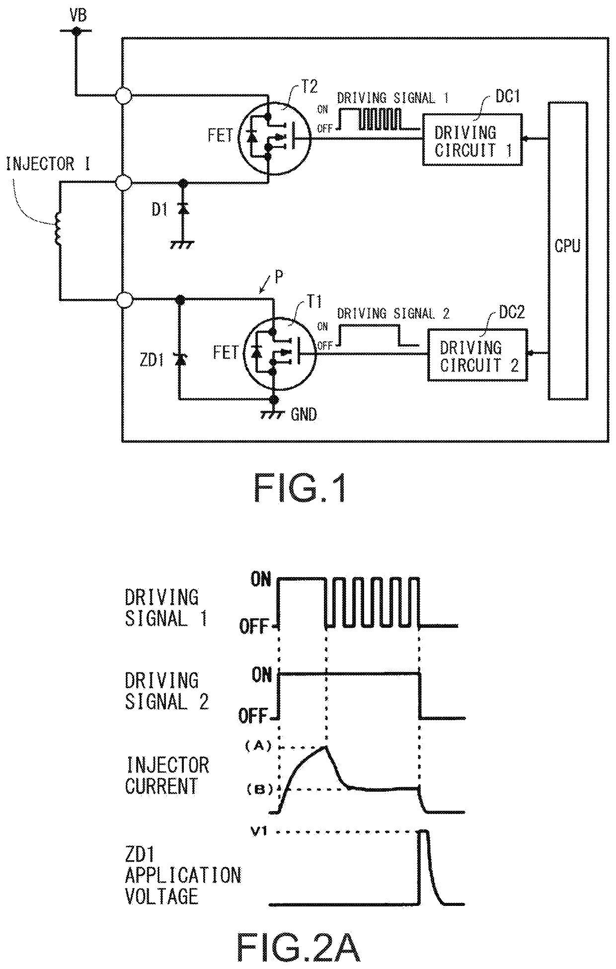
[0017]FIG. 1 is a circuit diagram illustrating a main part of an injector driving circuit used for carrying out a control method by the invention, and the invention can prevent an increase in size of a component and an increase in price by preventing damage to a Zener diode for reducing back electromotive voltage energy due to the injector in an OFF state even when a conventional component is used, which is basically in common with a conventional driving circuit.

[0018]In addition, the control method is the same as that in the conventional example in a normal time, and a detailed description thereof is omitted.

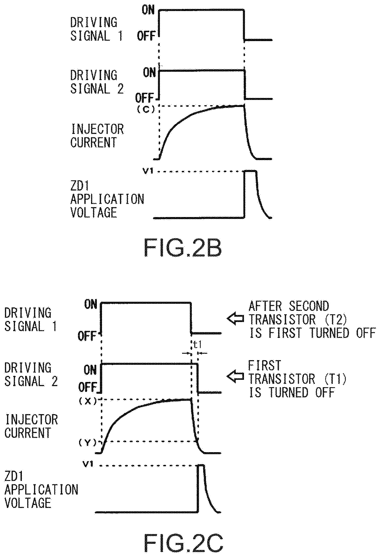
[0019]In addition, the present embodiment is similar to the conventional control method illustrated in FIG. 2B in that valve opening torque is increased to open an injector by turning ON both the first FET T1 and the second FET T2 in an ON state to obtain a maximum current when a vehicle is ...


PUM


Abstract

A method of controlling an injector driving circuit that may include a first field effect transistor (FET) that opens and closes a driving power supply to an injector, a second FET having a pulse width modulation control function for supplying a starting current to the injector to open a valve and then supplying a driving current for maintaining an opening driving state to the injector, and a Zener diode. The method may include increasing a valve opening torque to open the injector via turning ON both the first and second FET to obtain a maximum current during a cold start or when an injector valve sticks, turning OFF the second FET before closing the injector, and preventing damage to the Zener diode due to a back electromotive voltage from the injector provided when the valve is closed via turning OFF the first FET after a predetermined amount of time elapses.

Description

BACKGROUNDTechnical Field[0001]The present invention relates to a method of controlling an injector (fuel injection valve) driving circuit that injects a gas fuel into each cylinder, for example, in a gas fuel engine of LPG, CNG, etc.Related Art[0002]An injector used for a gas fuel engine of LPG, CNG, etc. needs to inject a large amount of fuel such as natural gas fuel in a short period of time. An injector driving circuit is configured to supply a starting current of a value set in advance at a beginning of a valve opening time to the injector for a set time, and then pulse width modulation (PWM)-control a holding current having a value greater than or equal to a value necessary to retain an open valve state to supply the holding current to the injector. For example, the above description is disclosed in JP 63-35827 B, JP 8-144859 A, JP 11-294262 A, etc.[0003]FIG. 1 illustrates a main part of the conventional injector driving circuit, and an injector I opened and closed by a soleno...

Claims


Application Information

Patent Timeline
IPC IPC(8): F02D41/30H02H7/00H03K17/0812F02M51/06F02D41/22
CPCH03K17/08122F02D41/221H02H7/008F02M51/06F02D41/3005F02D41/064F02D41/20F02D2041/202F02D2041/2068F02D2041/2075
Inventor YAMADA, TAKAHIROINO, TAKUYA
Owner NIKKI CO LTD
Features
  • R&D
  • Intellectual Property
  • Life Sciences
  • Materials
  • Tech Scout
  • Unparalleled Data Quality
  • Higher Quality Content
  • 60% Fewer Hallucinations
Learn More